De
De 

-
-
-
-
-
-
-
-
-
-
-
-
-
-
-
-
-
Visual Styles
-
-
-
-
-
-
-
-
-
-
-
-
-
-
-
-
-
-
-
-
-
-
-
-
-
-
-
-
-
-
Visual Styles
nanoCAD allows you to set methods (styles) for displaying three-dimensional objects in the current viewport. You can change the visual style of a viewport in the Properties bar in Miscellaneous section, or by using the view control widget at the top of the viewport.
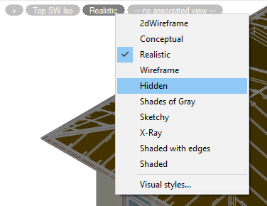
Predefined visual styles:
2dWireframe – the style is intended to work with flat drawings. Only edges are displayed as lines and curves that represent surface boundaries. Fills and hatches are not displayed. The type and weight of lines are taken into account. Raster and OLE objects are visible. See below for more details on the visual style.
Conceptual – objects are displayed using smooth shading and Gooch face style. Gooch's face style is characterized by transitions between cold and warm, rather than between dark and light shades of colors. This effect is less realistic, but it better represents the model details.
Realistic – objects are displayed using smooth shading and showing materials.
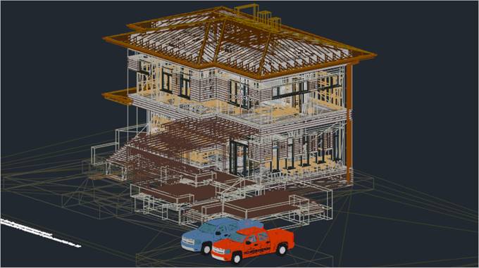
Wireframe – only edges are displayed in form of lines and curves that represent the boundaries of surfaces. Line type and weight are not taken into account, raster objects are not displayed. When using materials, the color of lines is determined by the color of material. Draw order and fill options from 2D solids are not displayed.
This visual style does not result in repeated creation of the view when its direction changes, as is the case with the 2dWireframe visual style. In large 3D models, the time savings will be significant.
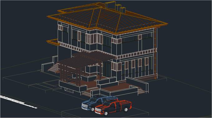
Hidden – objects are represented as a wireframe. Unlike the Wireframe style, edges hidden by opaque surfaces are not displayed.
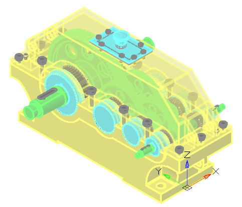
Shades of Gray – objects are displayed using shades of a single color (gray) with smooth transitions.
Sketchy – objects are displayed with a freehand drawing effect, taking into account the Line Extend and Jitter edge modifiers.
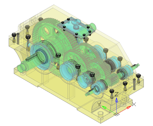
X-Ray – objects are displayed partially transparent.
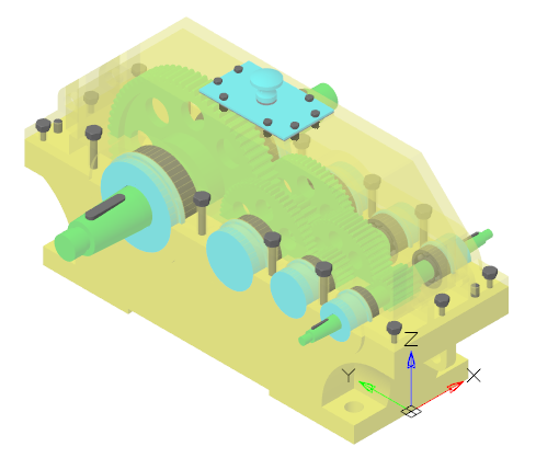
Shaded with edges – objects are displayed using smooth shading with visible edges.
Shaded – objects are displayed using smooth shading with no overtly defined edges.
Feature of 2D Wireframe Visual Style
This style is intended for working with flat drawings. Only edges are displayed as lines and curves that represent surface boundaries. Fills and hatches are not displayed. The type and weight of lines are taken into account. Raster and OLE objects are visible.
The 2D Wireframe style settings are not editable in the Visual Styles Dialog Box and cannot be used to create a user defined style.
Work with incorrect z-coordinates
When 2D Wireframe style is used in conjunction with a top view, the z-coordinate values are ignored when displaying and redrawing the drawing. This allows you to quickly display and work with incorrect documents, which are flat drawings, the objects of which have a spread of coordinates in height, often very significant. As a rule, such a spread appears after incorrect conversion of 2D drawings to 3D DWG format by third-party CAD systems. If other visual styles are used, such drawings may take a significant amount of time to display and redraw.
NOTE: To correct (zero) the z-coordinates of objects in such drawings, use the AUDITGEOMETRY geometry check command.
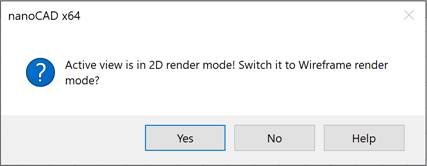
Work with point clouds
2D Wireframe style is not designed to work with point clouds. When importing point clouds into a viewport with 2D Wireframe style set, you will be prompted to automatically switch to Wireframe visual style, which you should accept.