
 De
De 

-
-
-
-
-
-
-
-
-
-
-
-
-
-
-
-
-
-
-
-
-
-
-
-
-
-
-
-
-
-
-
-
-
-
-
-
-
-
-
Creating Customized Library of Conventional Signs
-
-
-
-
-
-
-
-
-
-
-
Creating Customized Library of Conventional Signs
Structure of a Library of Conventional Signs
· Files of the library of conventional signs (hereinafter - CS) re located in the folder: “C:\Users\*USER NAME*\appdata\Roaming\Nanosoft AS\nanoCAD x64 21.0\classifier\”;
· The “\icons” folder contains icons for symbols in the Library of Sings bar;
· The “\support” folder contains databases of blocks, linetypes, multilines, forms;
· The DwgLib.dwg file in the “\support” folder contains blocks of the preset library; the Topo500.mln, Topo500.lin, ltypeshp.shx files store the description of linetypes, multilines and forms;
· The Classifier.xml file contains the description of the preset library, which is loaded into the bar by default. It cannot be disabled, but can be edited;
· When adding new libraries in the form of *.xml files, their connection will become available through the interface of the Library of Sings bar.
Creating a Customized Library Using Teplate
Put the “Additional conventional signs.xml” template file in the “c:\Users\*USER NAME*\appdata\Roaming\Nanosoft AS\nanoCAD x64 22.0\classifier\” folder
Main elements of the XML file:
· group – a folder (or subfolder) in the bar tree;
· object – object (point or line CS). The description of classifier objects is discussed below.
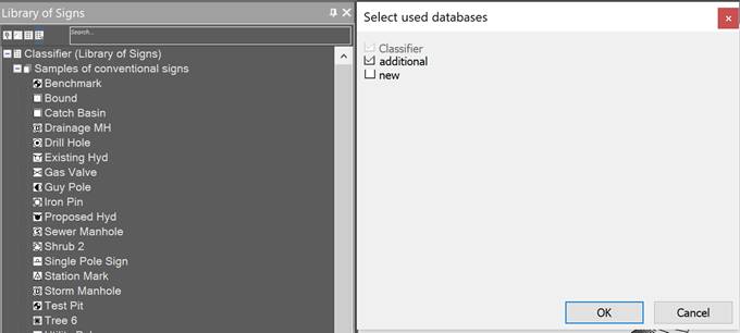
Open the Library of Signs bar (WS_CLASSIFICATOR command) and connect the additional library:
Adding Conventional Signs to the Library
Open the drawing from which you plan to add conventional signs.
In the bar tree select the section to which you want to add a new conventional sign. If, when creating an element, the name of the library is selected in the bar tree, then the CS will be added to the classifier without a folder (to the root of the tree).
Click the  Create elements button.
Enter the element information in the command line:
· element name in the classifier;
· name of the layer on which the element should be placed when it is inserted into the drawing;
· possibility to scale the element;
· type of object.
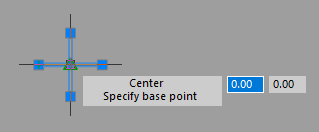
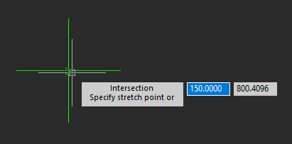
In the drawing, select the objects that make up the element and set the insertion point:
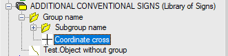
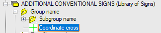
The new object will appear in the list of conventional signs of the bar:
Description of a point sign in XML file looks like:
<object name="Coordinate cross" id="60002" cmd="block" internal="WS_Point" args=""
ScaleMode="fixed" CType="block">
<params>
<layer>Design</layer>
<source>60002</source>
<description>Coordinate cross</description>
</params>
</object>
Required elements:
· layer – defines the name of the layer that will be created when inserting the CS;
· source – name of the DWG file in which the block and block name are stored, respectively;
· name – defines the sign name in the bar tree;
· internal – nanoCAD command called when inserting a conventional sign. Values:
· WS_Point – command for inserting a point CS;
· WS_Line – command for drawing a polyline or multiline.
Using this, you can add a sign description directly to the XML file.
Adding line signs (polylines and multilines)
To add a new conventional sign in the form of a polyline, first add a description of this polyline to the Topo500.lin file.
To add a CS as a multiline, add a description to the Topo500.mln file.
Adding line conventional signs through the bar interface is not yet provided, so you need to edit the XML file directly. The description of the line sign in the XML file looks like this:
<object name="Line sign" id="NN" cmd="block" internal="WS_Line" args="">
<params>
<layer>Line sign</layer>
<grStyle>NN</grStyle>
<lweight>60</lweight>
<color>10</color>
</params>
</object>
Required elements:
· layer – defines the name of the layer that will be created when inserting the CS;
· grStyle – the name of the line style in the LIN (MLN) description file;
· lweight – line weight of the conventional sign;
· color – line color of the conventional sign.
The useColors attribute at the beginning of the XML file is responsible for using the color. Values:
· true – conventional signs will be inserted taking into account the specified color;
· false – all new signs will be inserted in the default color (by layer).
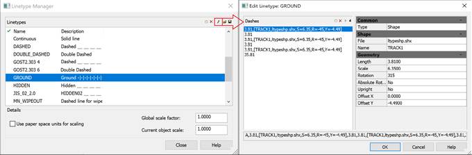
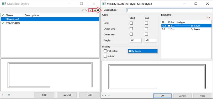
nanoCAD has built-in editors for line types and multiline styles (LINETYPE and MLSTYLE commands), in which you can conveniently change the existing lines or create new ones in Topo500.lin and Topo500.mln files. These editors also allow you to specify the line style name for manual editing of XML files.
Editing the Existing Conventional Signs of the Library
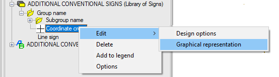
To edit point sign graphics, open the context menu by clicking on the bar, and select Edit -> Graphical representation:
Upon the prompt Select objects or [?]: specify elements of a future sign in the drawing and set its base point:
Sign editing is completed. In the library tree, the CS icon will be updated:
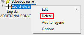
To delete signs from the bar, use the context menu:
Using the above format for describing a point CS in an XML file, you can edit the sign in the XML file directly by replacing the sign’s name (if there is a ready-made file with such a block) or delete the object completely.
Editing the outline of line conventional signs through the bar interface is not yet provided, to change such signs you should edit the XML file.
When manually creating or editing sign graphics via the XML file description, the sign icons for the bar should also be created manually. In order for objects to get an icon, it is necessary to create a BMP file with a sign image (16x16 pixels in size and 32 bit color depth) and put it in the “\icons” folder. The name of the BMP file should match the element name in the description of the sign (block, line type, multiline). After restarting nanoCAD, the icons will appear in the bar.