


 De
De  Es
Es  Fr
Fr 

-
-
-
-
-
-
-
-
-
-
-
-
-
-
-
-
Properties Panel
-
-
-
-
-
-
-
-
-
-
-
-
-
-
-
-
-
-
-
-
-
-
-
-
-
-
-
-
-
-
-
-
-
Properties Panel
 Ribbon: Home –Properties >
  Properties
Menu: Tools –  Properties
Menu: Modify – Properties
Menu: View – Toolbars > Functional > Properties
Toolbar: Main –
 Hotkeys: CTRL+1
Command line: INSP, INSPECTOR, PROPERTIES
The Properties bar is used to display information about selected objects, to change objects’ properties, to specify a selection mode and call up selection commands.
The list of properties is separated into groups. Manage the visibility of properties of any group by using the  and
and  buttons in the group name. The button shows the properties for the hidden group. When this button is selected the properties list of the group is shown and the button switches to the button.
|
|
The different properties of objects are displayed in the left column in the Properties bar; their values are shown in the right column. Information in the Properties bar depends on the current command and different parameters of the selected objects are shown. If no object is selected, No selection is shown in the Object type field:
|
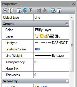

Current setting parameters for the properties of created objects of the document are shown in the General group. For example, the Line Weight has a «1.00» value, so new lines, arcs and circles will be created with this weight.
|
|
If several objects of one type are selected, their type and number (in brackets) are displayed in the right column:
If several objects of different types are selected, All (2) is displayed in the Objects type field:
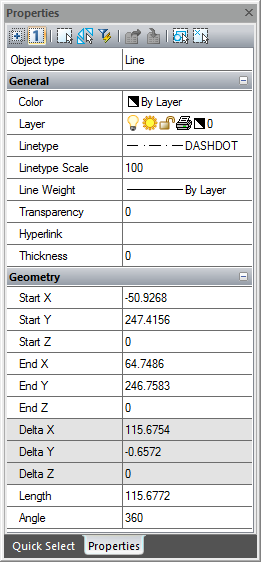
The General group contains information about an object’s properties: color, layer, line type etc. The Geometry group displays information about the geometric parameters of an object and its position in the document. Properties that can be changed are shown in black in the left column. You can specify new values for these properties in the corresponding fields. Values outside of the limits are not used automatically. The grey color is used to display information about properties which cannot be changed and for properties depending on other properties. If several objects are selected, only properties common to all the objects are displayed.
|


If any property does not have a value (the field in the column is empty); two or more objects having the property among selected objects, but the values of the property are different, for example center coordinates for two non-concentric circles:
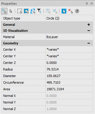
The value, entered in such a field, is one for this property for all objects selected, if it can be applied.
In unlocked value input fields (for properties of REAL type) it is possible to calculate mathematical expressions (for more information, see the Math Processor section).
Layers and objects that have property overrides in viewports are highlighted in blue:
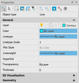
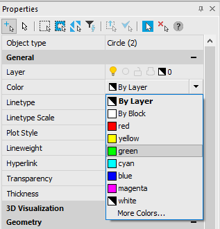
Some properties of objects, such as, color, line type, and line weight can be selected from the drop-down list:
To change the properties of objects in the Properties bar:
1. Select one or several objects.
2. Click in the left column of the property that you want to change.
3. Select the required value in the drop-down list to the right of the column or type a new value.
4. To apply a typed property value to the objects, press ENTER. Values, selected from a list, are applied to the selected objects immediately without pressing the ENTER button.
5. To deselect objects, click in the drawing area or press ESC.
There are mode and selection command buttons in the top part of the Properties bar:
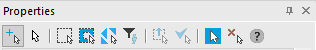
Description of modes and selection commands, ways of selection for object see in the “Selection of objects using the Properties bar” section.