
 De
De  Es
Es  Fr
Fr 

-
-
-
-
-
-
-
-
-
-
-
-
Audit Geometry
-
-
-
-
-
-
-
-
-
-
-
-
-
-
-
-
-
-
-
-
-
-
-
-
-
-
-
-
-
-
-
-
-
-
-
-
-
-
-
-
-
Audit Geometry
 nanoCAD button – Utilities >
 Audit Geometry
Manu: File – Drawing Utilities >  Audit Geometry
Context menu of document tab: Drawing Utilities > Audit Geometry
 Command line: AUDITGEOMETRY
The command is intended to identify and fix problematic drawing objects located outside the range 1e+20 along Z axis.
The command ensures correction of Z-coordinates for objects located on frozen, locked and disabled layers.
The first opening of a file is accompanied by an automatic check of objects geometry. When geometry errors are found, a dialog is displayed with a message and a choice of action
|
Fix |
- immediately run the Audit Geometry command to fix errors. |
|
Cancel |
- open the file without correcting errors. |
Fix - immediately run the Audit Geometry command to fix errors.
Cancel - open the file without correcting errors.
If errors are not fixed, when files are opened again (after re-saving), the geometry audit is started by the command manually.
note: Hatch audit is not performed in an automatic mode. To find and fix problematic hatches, it is necessary to run the audit manually.
Audit modes:
|
Audit Z_coordinates |
Auditing Z-coordinates of all objects in a drawing. |
|
Audit_Hatches |
Auditing the correct display of hatches within the boundaries of contours. |
Audit Z coordinates
Audit options:
|
Yes(fix_errors) |
Fixes the errors found. |
|
Yes(fix_and_log_errors) |
Fixes errors and generate report on found and fixed errors. |
|
No |
Does not fix errors. |
|
No(only_log_errors) |
Creates a report on detected errors without fixing them. |
Detected and fixed errors are reported in the Geometry audit log dialog
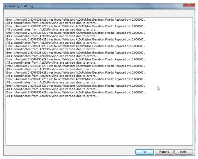
By clicking the Log dialog button, you can save the log information to a separate file. By default, the Log file is saved in a drawing folder and assigned with the drawing file name with *.log extension.
When saving reports of consecutive audits of Z coordinates and hatches for one drawing, 2 log files will be created:
· first - File name.log;
· second with adding the index - File name_1.log.
Command prompts:
|
Select audit type [audit_Z_coordinates/Audit_hatches] |
Select Audit_Z_coordinates mode. |
|
Do you want to fix errors? [Yes(fix_errors)/Yes(fix_and_log_erros)/No/No(only_log_erros)] |
Select the required audit option. |
Audit Hatches
|
Select audit type [audit_Z_coordinates/audit_Hatches/] |
Select Audit_hatches mode. |
Audit logs are displayed in the command line.