
 De
De 

DESIGNING
 Main menu: Mechanical - Design -
  Threaded fastening.
Ribbon: Mechanical - Design - Threaded fastening.
Toolbar: "Design" - Threaded fastening.
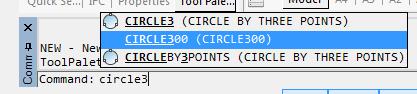
 Command line: MCJOINT.
Tool for inserting a threaded fastening from library nanoCAD Mechanica 23.
1. Specify the starting point of the threaded fastener in the drawing.
2. Specify the end point of the threaded fastener, the "Fasteners" dialog will open. When inserting, tools are available to select the direction of drawing. Specifying the start and end points defines the centerline of the fastener. The intersected lines make up the thickness of the part package being fastened.
3. In the "Fasteners" dialog box, customize the look of the threaded fastener.
|
Note: |
The thread fastener insert dialog automatically saves the last selected template and thread diameter. |
4. Confirm the settings with the "Apply" button, or with the "OK" button if you want to close the dialog at the same time. A threaded fastener will be built.

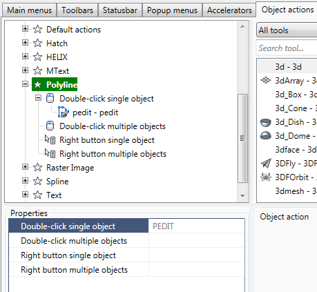
You can edit a threaded fastener by editing the "Threaded fastener" object, or by editing individual parts included in the threaded fastener.
When editing, you can change the composition, diameter of the threaded fastener, as well as the parameters of the individual parts that are included in it.
To open the threaded fastener setup dialog, apply any of the standard editing tools to the centerline of a group of parts.
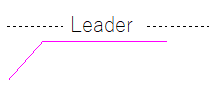
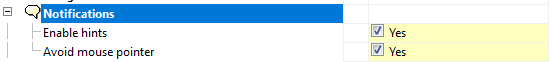
If tooltips are enabled in nanoCAD Mechanica 23 settings, then when you hover the cursor over the centerline, the "Threaded fastening" tooltip appears.
Threaded fastener settings dialog box
Template list panel
It is possible to save a threaded fastener template for later reuse of assemblies with the same set of parts. To work with templates, use the buttons at the top of the dialog box, and below is a list of available templates:
Button  "Create new template" adds a new empty template. When creating a new template, the required number of holes is automatically added depending on the number of lines crossed in the drawing.
Button  "Delete template" removes the selected template from the list. "Editing template" stores the current setting of the threaded fasteners. It cannot be removed.
Button  "Selecting insertion point" is intended to reselect the insertion point and the length of the threaded fastener in the drawing.
Button  "Manually select holes length and placement" opens a window for setting parameters of a package of connected parts.
LMB clicking on one of the cells in the "Parts type" column switches the part / gap:
In the "Parts width" column, the thickness of the corresponding part (or gap) is set. After setting the parameters of the connection package, close the window with the "OK" button.
The context menu of the list of templates contains the commands:
· Add folder
· Delete object
· Rename
· Import object
· Export object
· Send by email
· Copy
· Configuration tool
These commands are similar to those used in the object manager nanoCAD Mechanica 23.
Tab "Template"
The following settings are available on the "Template" tab in the center of the dialog:
· Fasteners properties
· Package thickness - thickness of the package of parts to be joined, in mm.
· View - selection of standard image projection.
· Small thread pitch - fine pitch switch.
· Simplified view - simplified / full image switch.
· Details of the threaded assembly. The components included in the assembly are listed here in order.
· Screw
· Hole
· Spot facing
· Washer
· Nut
To select a part of a threaded assembly from the nanoCAD Mechanica 23 base, click in the cell of the GOST column of the corresponding element.
The "Select object" dialog box will open the attachment parts folder.
Additional settings for assembly components are available when expanding the list:
Button "Clear" in the right column of the list table clears the selected position.
Tab "Preview"
A preview of the threaded assembly is available on the tab.
List of thread diameters
|
|
The "lightbulb" icon above the list indicates that the selected diameter value can be used for all objects in the assembly: |
 The diameter value does not match one or more parts. Assembly is not possible.
 The diameter value applies to all parts in the assembly. Assembly is possible.
Button  "Add part to template"
Adds a part to the assembly after being selected from the list. The list of details available for adding depends on the currently selected object:
Button  "Remove part from template"
Removes the selected object from the parts list.
Button  "Dynamic selection"
Turns on the mode of visual selection of the bolt length after closing the dialog.
Graphical display type selection list
When inserting a threaded fastener, 3 display methods are available, selected by the "Select fasteners insert part" button on the bottom toolbar of the dialog. The figure on the button displays the currently selected display method:
|
With local out |
Normal insert type |
Insert hidden fastener |
|
|
|
|


To select the options for displaying chamfers in the drawing, you must correctly place the marks in the hole properties.
To change the hole type, click on it in the connection part set and select a different type in the "Select object" dialog box that opens.
Main menu: Mechanical - Design -  Rivet joint.
Ribbon: Mechanical - Design - Rivet joint.
Toolbar: Rivet joint ( "Design").
Command line: MCRIVET.
Insertion tool riveted joint parts of the base standard elements nanoCAD Mechanica23.
1. Specify the starting point for drawing the rivet assembly.
2. Specify the endpoint of the rivet assembly. When you insert the available tools of choice destinations rendering .
3. In the dialog box mounting parts adjust the view of the rivet connections.

To select the type of rivet base nanoCAD Mechanica23 click in the rivet.
To select the type of base openings nanoCAD Mechanica23 click in the hole for rivets.
It is possible to save the template riveted joint for later reuse assemblies with the same set of items. To work with templates use the buttons at the top of the dialog box, and below is a list of available templates:

"Editable Template" stores the current settings bolting. It can not be deleted.
Button  Create a new template. Adds a new blank template.
Button  Delete template. Deletes the selected template from the list.
In the context menu templates available commands:
· Add Folder
· Delete object
· Rename
· Import from file
· Export to file
· Send by email
· Copy
These commands are similar to those used in in the Object Manager nanoCAD Mechanica23.
Button  Select the insertion point and the length of the riveted joint. Designed to re-select the insertion point and the length of the rivet assembly drawing.
Button  Set package connection manually. Opens setup package of the parts.
Left-click on one of the cells in the column "type items" to switch the item / gap:
In the "Thickness" is set to the thickness of the relevant part (or gap) After configuring the package connected, close the window by pressing OK.
The right side of the dialog box mounting parts is a list of values diameter rivets.
When you insert the rivet connections are available 3 ways to display selected button Insert mode riveted joint at the bottom of the dialog box toolbar. Drawing on the button displays the currently selected display method:
 With a local cutaway
 Normal Box
 Insert hidden
2 types available (front and side) display riveted joint:
 Front view
 Left side view
You can choose the type rivet connections:
|
|
The number of types depending on the type of rivet. |

Automatic detection of packet connection
When you insert the rivet connections made automatically recognize the boundaries of the parts. If the line crosses the insertion direction perpendicular to a few segments in the drawing, they are defined as the boundaries of parts and installs Connection:
Insertion point and the length of the rivet assembly are determined automatically based on the thickness of the package details.

Editing riveted joint
A dialog box settings riveted joint, apply any of the standard editing tools to the centerline of the group details.
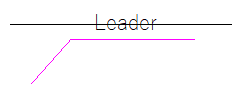
If the settings nanoCAD Mechanica23 included tooltips, then when you move the cursor to the center line will show "Rivet connection".
Main menu: Mechanical - Design -  Delete parts.
Ribbon: Mechanical - Design - Delete parts.
Toolbar: Design - Delete parts.
Command line: MCDELSPART.
The function is intended to remove the fastener bolt or rivet connections. Openings by bolted or riveted to remain on the drawing and in the object manager.

To remove fasteners bolting need to run the function and choose the item that came bolting.
The remaining holes.

Main menu: Mechanical - Design -  Create shaft.
Ribbon: Mechanical - Design - Create shaft.
Toolbar: Create shaft ( "Design").
Command line: MCARBOR.
After invoking the command, pick an insertion point.
Set the shaft direction by moving the mouse.
Left clicking creates a shaft segment.The command remains active and allows additional segment to be drawn.
Construction site 23 auto-detects the insertion point of a graphic element which is to be inserted, and acquires its geometry from a standard database.The auto-dected elements are highlighted in color.After the insertion command has been invoked, elements are highlighted at the mouse movements.Left-click to confirm.
Dialog box Editg shaft
|
|
Show / Hide section Standard fittings and details sections |
|
|
Add element |
|
|
Insert Group |
|
|
Edit Object |
|
|
Insert design |
|
|
Add view / section |
|
|
Scale of details and shaft sections |
 Shaft section displays methods
Composition tab "Standard fittings and details" is defined folder structure in the system folder "shafts" Database Construction Site 23.

In addition, in the tabs of the Edit shaft dialog are included
· Tooth-wheels
· Efforts
· User folders
Path to these elements are specified in the option Construction Site 23 (Standard Elements >Edit shaft ).
Click on the symbol "Plus", a list of components for editing.
When you specify a string in the column names in the drawing selected component is highlighted.
To modify a standard component, double-click the left mouse button on the name of GOST. In introducing the new values for the editable portion of the shaft all the changes are immediately displayed in the drawing.
Purpose size details in the dialog box
To select the size of the base bearing the dialog window Edit shaft.
Specifying the column name to GOST bearing, check option; bearing the figure should highlight.
Double click the left mouse button on the designation of the bearing or click once on the icon to edit  .
.
In the dialog box, this bearing sizes choose. Selection window will size bearing.
Complete the command by pressing OK and close the dialog box.
Similarly edit all items bearing assembly.
The quickest way to selecting the size of parts - a dynamic view of all of its dimensions by moving the mouse pointer to the left-right and up-down.
Specifying the insertion point of the bearing on the shaft, select size bearing.
When you move the pointer of the available bearing sizes select those that meet the internal diameter of the shaft and the combination of the bearing width and outer diameter correspond to the current cursor position.
Export shaft to an external file
For detailing received shafts can be exported to an external file. Double clicking the left mouse button on the shaft axis edited activate dialog Editing shaft.
In the dialog box, display the Edit and select from the drop down list of commands string Export to a file.
Then you want to fill the frame and title block specify the file's location.
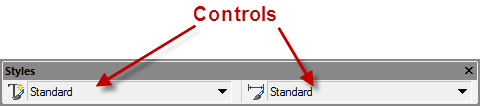
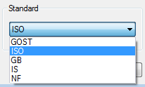
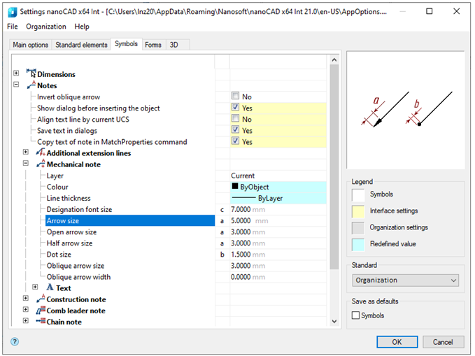
In the settings  select Standard, and set the desired spacing.
After setting the insertion point of the shaft when rendering, you can use a dialog box to set options stage:

After clicking on the shaft , you can choose the types of shaft ends.
Determining the size of shaft section in the status bar
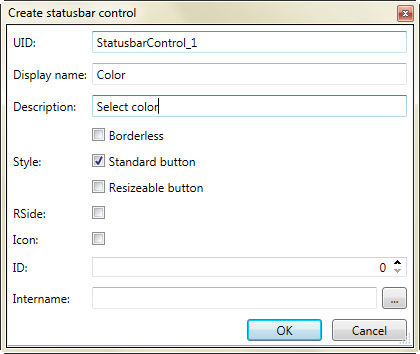
When rendering stage shaft in the status bar nanoCAD in the lower left corner of the window displays its properties.
Determining the size of shaft section in the dialog box
When you specify a dynamic image stage shaft, the right-click context menu and enter the D-line dialogue.
A dialog box shaft , in which you can enter the exact values of the diameter and length of the shaft portion.
How to edit areas of the shaft?
Edit shaft areas in several ways:
"Visual Editing": select an editable area and dynamically change its geometrical dimensions.
Specifying the exact plot sizes in the dialog box, double-click on the axis of the shaft left mouse button and change the section of the shaft in the dialog box Editing shaft.
Another way to call the same dialog box - point to the shaft axis and click the right mouse button.
When placing grooves retaining rings for automatic recognition of the diameter of the shaft and the insertion point on the shaft must first be placed bearing.


To specify the position of the groove snap ring must be attached to the shaft or to the end of the bearing. Automatically set the dependence on the position and diameter of the retaining ring \ grooves.
Placement of the retaining ring
When placing the retaining rings for the automatic recognition of their size on the shaft must be pre-arranged groove.

To indicate the position of the ring is enough when you insert attached to the groove (it is highlighted in the appropriate color).
For details of accommodation "cover" is necessary to consistently left-clicking on the bearing, and then on the shaft portion. Automatically creates a cap with the attached parameters of the situation, the diameter of the bearing and the shaft diameter.
When placing parts "Glass" is necessary to specify the series bearing cap.
Choose from a glass base nanoCAD Mechanica 23 part, direct the cursor on the bearing - he highlighted. Click with the left mouse button.
It is further proposed to select the cover - direct the cursor on the cover, it is highlighted - click the left mouse button.
In the dialog that appears, click OK insertion cup.
In the design of supports shafts are encouraged to use the mechanism of group insert multiple pieces of bearing select the desired template. If no suitable template support, it can be created. This technology is similar to technology insertion into a drawing fasteners from the selected template.
The pattern of support may include the following parts: bearings, wear rings, bushings, glass retaining ring grooves for them, locking cover, parts of gears and other parts of the base of standard parts.
Having a set of templates with a single command, you can immediately draw the option selected in the drawing of bearing.
Insert the template bearing support
Double click the left mouse button on the axis of the shaft of the edited call the corresponding dialog box. At the bottom of the window, click on the icon Insert group .
.
In the dialog box, select the folder Editing shaft gears and select a template cylindrical gear shaft.
After selecting the parts "cylindrical gear shaft" mouse pointer is displayed as a standard cross-hair, blue arrows and the image of a small green square (standard view). When you hover the pointer on the shaft, this area will be highlighted in green and contains the insertion point of the ring gear.
In the dialog box, spur gear option
Take the rate you need to click on the drop-down list of the calculations and indicate which item you want to transfer
render (or gear wheel).
The option is available if a calculation has been created. To insert an object into a chain of objects, click OK. After applying the gear, the cursor pointer takes the standard form. It is further proposed to continue drawing the next part of the engagement.
Drawing on the results of the calculation of gearing
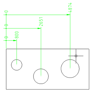
Original drawing:
Double click the left mouse button on the axis of the shaft, call the dialog box Editing shaft.
Tab gears.
Select a template cylindrical gear shaft.
By clicking the left mouse button, set the insertion point on the lower shaft gear.


Move the cursor pointer to the wheel on the upper shaft (ring gear is highlighted in green). Left-click to confirm your choice.
In the drop-down list of the calculations, specify the desired (in our example - calculation with the name of "Example of calculation") and select what should render the lower portion of the shaft (in this example - "Gear").
Click the OK button. At the request of the "Insert object in the chain of objects?" Answer "yes".
Press ESC to finish drawing commands engage and close the dialog box.
As a result, the drawing rendered pair of gearing with deposited assembly dependencies.
Main menu: Mechanical - Design - Shafts - 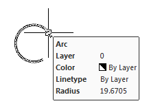 Shaft chamfer.
Ribbon: Mechanical - Design - Shaft chamfer.
Toolbar: Shaft chamfer ( "Design").
Command line: MCACHAMFER.
To insert a chamfer is necessary to run a command and select the portion of the shaft.

The chamfer is automatically adjusted to the diameter of the shaft portion. Fixing chamfer happens when you click the mouse, and then open dialogue Bevel-rounding.
After closing the dialog construct chamfer automatically.
Main menu: Mechanical - Design - Shafts -  Shaft fillet.
Ribbon: Mechanical - Design - Shaft fillet.
Toolbar: Shaft fillet ( "Design").
Command line: MCAFILET.
To insert, you must run the command interface and mating portions of the shaft.
Fixing interface brings up a dialog transition.

After closing the dialog interface to build automatically.

Design of pipelines for internal and external cone
 Library: Pipe fittings.
For example:
Pipe fittings - Connections on External Cone - GOST 139xx-74 - Pipes
Pipe fittings - Connections on Internal Cone - GOST 160xx-70 - Pipes
...
First - automatic connection of two pipe fittings elements.
When joining the program selects the shortest distance: pipe length is calculated from the minimum values of the linear section and minimum bending radius of the pipe diameter.
The parameters are set in the pipeline nanoCAD Mechanica 23 (team Settings).

To automatically connect the two valve elements specify the connecting member (bushings, elbows, tees, crosses), hold down SHIFT. nanoCAD Mechanica 23 generate trajectory tubes and displays the dialog box with the geometric size of the segment of the pipeline. If the proposed path will not suit you, it can be edited in the same window.
Second - step by step construction of the pipeline with a consistent set the direction and length of the pipe segment.
Step task trajectory pipe begins with the first element of the valve. The insertion point and pipe diameter are determined automatically.
Next, follow the prompts on the command line, you can create the path of the pipeline, consistently introducing straight and arched portions.
For automatic connection of the pipe end to an element of reinforcement necessary to open the context menu.
Select option C bonds and provide an element of reinforcement with which to make the connection.
Call the following context menu again by pressing the right mouse button.
Select it as the pipe sections need render.
The compound can be performed in three or five sections.
By clicking the right mouse button to complete the command.
Apply hole.
Insert from a database element "Pipe".
Choose from a database element "Hole taper thread."
Specify the coordinates of the conical hole.
In the opening taper threaded set nominal thread. On the second tab, Properties , set the length and diameter of the hole drilling.
Complete the command by pressing ESC.
Place details of the reinforcement.
Assembly according to angles and taper thread throughs applied automatically.
Insert from a database element "Pipeline fitting".
Choose from a database element "Unions".
Hover your pointer to the hole and click the left mouse button
Complete the command by pressing ESC.
For pipelines on external cone
Insert from a database element "Pipe" in Model.
Upon completion of the construction will be offered automatically add nipples and nuts to the ends of the pipeline.

If nipples and nuts have been added automatically, you need to place them manually.
Choose from a database element "Pipeline fitting".
Choose from a database element "Nipples".
Hover your pointer to the end portion of the pipe and left-click
Select size and click OK.
Complete the command by pressing ESC.
For pipelines on internal cone
When selecting the pipeline on internal cone selection dialog appears connects equipment automatically added to the compounds of the inner cone, depending on the type of environment and the type of nipple (spherical or hemispherical). For a spherical pin structure parts will be as follows:
· GOST 16043-70 nipple
· GOST 16048-70 lock ring
· GOST 16047-70 Bolting
For hemispherical pin composition details:
· GOST 16042-70 nipple
· GOST 16046-70 Bolting
Thread the other end of the pipeline construction include:
· Choose hardware - reappears dialogue "set of equipment."
· Building and - at the second end of the conduit parts to be added to set the same parameters and composition as the first one.
· Do not build - further details will not be built.
Example of construction of the pipeline on external cone
To the connection details automatically recognize your size and were object-dependent, the figure should be placed initially element reinforcement or opening.
In our example, we will adhere to the following order: Insert pipe nipple and nut.

Object "pipe" can draw only pointing out any element of reinforcement.
For applying object-dependent connection details on previously placed component is enough to point to the workpiece aperture cursor pointer. Base item is highlighted in color.

Automatic determination of size and pipe insertion point


Automatic determination of size and the insertion point of the pin

Automatic determination of size and the insertion point nuts
For piping design, you can use a tool group insert objects.
Dialog box Insert group and organize the group result.
To use her group must first create it. To do this, use the following steps:
· Added to the drawing details of the object manager
· Through dialogue Dependency Management, or automatically when you insert constrain standard parts are dependencies between components.
· Group is created through dialogue to create groups.
The group must be incomplete, ie does not include fittings or pipe.
Instead, when you insert the missing fittings group will be requested item (items) in the drawing.
Set the method of overlapping pipelines

We indicate the horizontal pipe as an object to which the selected throughs must be higher.

After clicking on the icon Overlapping objects get a new version of the layout.
Distinguish compounds and by right-clicking, we show in the context menu line Move Up. Horizontal pipe is above all the elements.
Creating a cross-section of a connection
Select the nut and invoke the content menu , choose send to back , Then choose the object behind which the nut should be placed.
Giving the command overlapping objects, we corrected geometry.
Editing pipeline trajectory by Grip Editing
Select a pipeline and use the grips to move the nodes.If a midpoint node is edited , the relocated tube is parallel to its original and its neighbouring segments are adjusted automatically.

Nodes located on the endpoints of linear segments may only be relocate along the axis of the current segment.
Double-clicking on a tube to open the edit pipe dialog:
To edit a trajectory using the step by step connector , first pick a tube segment. The segment will show in different color.
For linear section given length parameter is set.
For arc sections,the bent radious parameter is set.
The following sections of pipelines alignment options:
 Vertical alignment.
 Horizontal alignment.
 Object perpendicular alignment.
 Object parallel alignment.
 Object parallel alignment by distance.
 Undo last alignment
In addition, the following editing options:
 Base parameters change.
Editing tube properties , start the base parameters change command to set the material and geometry parameters of the tube in the dialog.
On the Properties You can change the display pipeline (filling, cut).

 Saving the pipe to an external file
After selecting this command, a dialog box title block. When information is entered in the title block, it is proposed to specify a filename and location.
 Extend pipe
This function connects the pipe to a fitting or to a free end of another pipe.
Main menu: Mechanical - Design -  Import *.idf (*.brd) files.
Ribbon: Mechanical - Design - Import *.idf (*.brd) files.
Toolbar: Import *.idf (*.brd) files ( "Design").
Command line: MCIDFCONVERT.
After calling the command, the system asks for a file with the extension *.Emn (export file format from the IDF Orcad) or *.Brd (export file format from the IDF PCAD).
Caution! To import of PCB with components also required a library of components that must be maintained with the same name and in the same directory as the file of the PCB. PCAD library file has the extension *. Lib, file libraries Orcad - *. Emp.
The system reads the information from the file. It is further assumed that the user can check and correct it with a dialog box IDF.
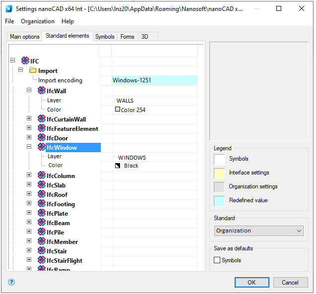
If by reference numerals may determine the type of element, the nanoCAD Mechanica 23 automatically assigns the appropriate circuit parameters and fill color (can be changed in settings).
Thickness (height) of the element is taken from the import file, and if it is not defined in it, the item is automatically assigned to one micron in height.
The user has the possibility to limit the detail card by disabling generation of the individual (or all) of the elements and hiding holes in the board.

After clicking the Apply or OK button - automatically generated drawing board. It is placed at the origin, and can thereafter be moved by the handles.
The Apply button allows you to continue editing the appearance and composition of the board with a graphical preview of the drawing.
PCB editing by double-clicking on it and in the same dialog box, change its structure or appearance.