
 De
De  Es
Es  Fr
Fr 

-
-
-
-
-
-
-
-
-
-
Dynamic UCS
-
-
-
-
-
-
-
-
-
-
-
-
-
-
-
-
-
-
-
-
-
-
-
-
-
-
-
-
-
-
-
-
-
-
-
-
-
Dynamic UCS
 Status bar:
  Dynamic UCS
 Hotkeys: F6
Command line: UCSDETECTCMD
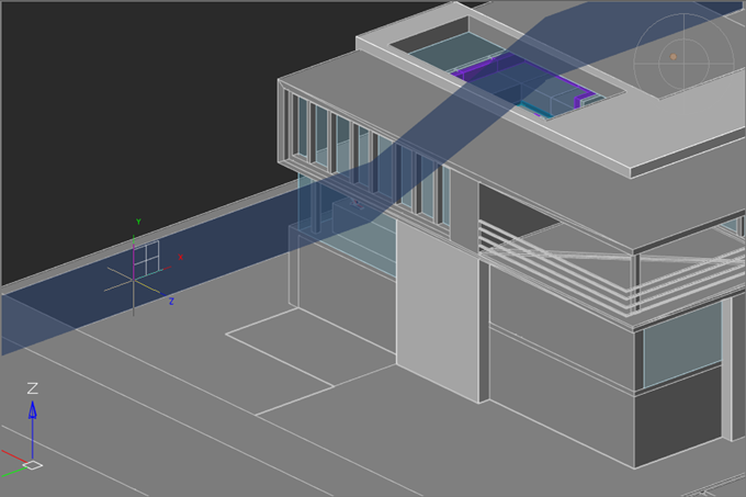
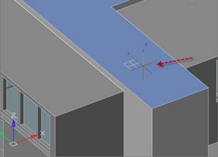
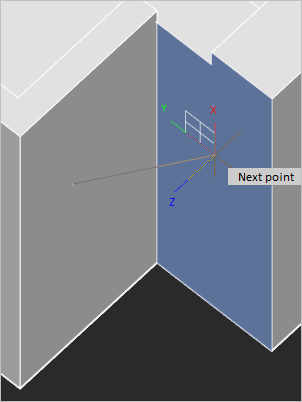
When you create an object and move the cursor over a flat segment, the UCS temporarily aligns with it. This makes it possible to immediately draw in the plane of the highlighted face without additional execution of change-UCS commands. This feature is available in the Dynamic UCS mode.
In the dynamic UCS mode, UCS changes its orientation when you move cursor over a face of a 3D solid or a flat segment of a point cloud.
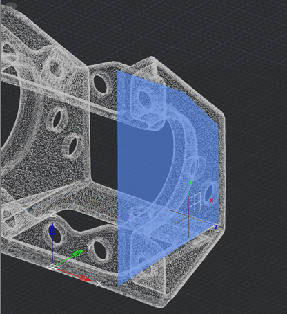
The dynamic UCS works on point clouds with surfaces, previously recognized by the  Search Planes in Point Clouds command.
To align the grid plane with the XY plane of the dynamic UCS, check the Follow Dynamic UCS box on the Snap and Grid tab of the Drafting Settings dialog box or use the GRIDDISPLAY variable.
|
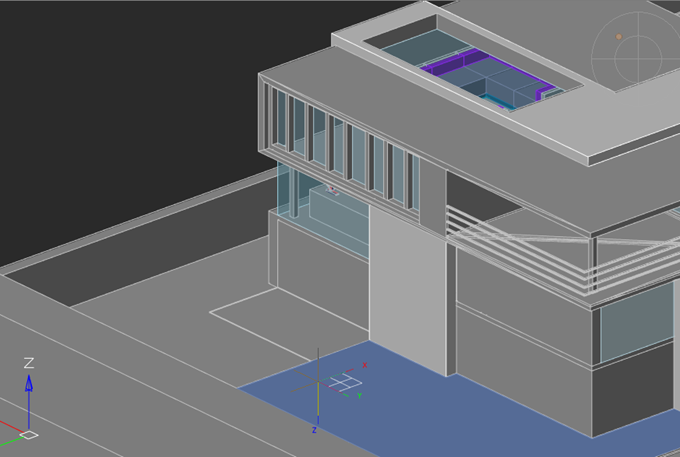
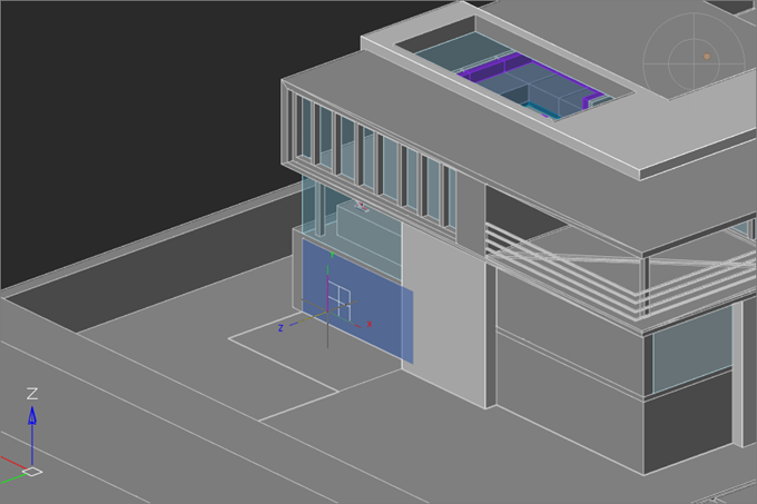
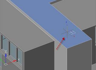
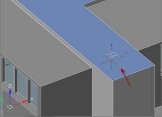
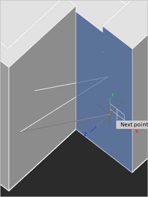
The direction of the UCS axes depends on the edge that the cursor crossed when moving to the face. So, the X axis is set parallel to the crossed edge in the direction from the initial vertex of the crossed edge. The Y axis perpendicular to the X axis and is directed toward the inner part of the face. Z axis is set so that the right coordinate system is obtained. When you move cursor toward the same face through another edge, the orientation of the UCS axes also changes. |
|
|
|
|
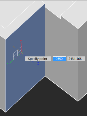
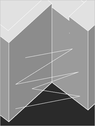
At the first mouse click, the UCS is fixed and the first vertex of the created object is set. Then you can continue to draw in the selected plane. Upon exiting the object creation command, the UCS is reset to its original orientation.
To change the UCS again when specifying another vertex while the construction command is running, you need to hold down the CTRL+~ key combination.
You can change the UCS when specifying each vertex without using keyboard shortcuts. To do this, assign the value 1 to the UCSDETECTMODE variable (default = 0).
Upon exiting the command to create a vector object, the UCS is reset to its original position.