
 De
De  Es
Es  Fr
Fr 

-
-
-
-
-
-
-
-
-
-
-
-
-
-
-
-
-
-
-
Layers Functional Bar
-
-
-
-
-
-
-
-
-
-
-
-
-
-
-
-
-
-
-
-
-
-
-
-
-
-
-
-
-
-
-
-
Layers Functional Bar
 Ribbon: Home – Layers >
  Layer Manager
Ribbon: Manage – Palettes > Layer Manager
 Menu: View – Toolbars > Functional >
  Layer Manager…
Toolbar: Functional – Layer Manager…
 Command line: LAYERSQUICK
The Layers functional bar is designed to manage layers and their properties:
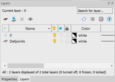
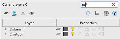
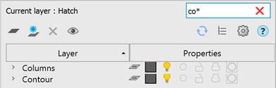
At the top of the toolbar, immediately under the title, the name of the current layer and the Search for layer field are displayed (the search is carried out by the layer name):
The field’s  Clear button resets the search results.
The bottom part of the toolbar contains information about the displayed layers, the total number of layers, the number of turned off, frozen and locked layers:

Below the name of the current layer there are buttons:
|
Adds a new layer. |
|
|
|
Adds a layer frozen in all viewports. |
|
Deletes the selected layer. |
|
|
Enables view mode for only selected layers. |
|
|
|
Regeneration. |
|
|
Changes the presentation format of layers and their properties in the bar. |
|
Manages the display options in the Layers bar and properties of layers included in external references. |
 Refresh
 table view
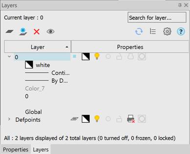
The list of layers can be presented in a tree or table view. By default, the display mode is set to a tree view.
Table view of the list of layers
The table view displays layer properties as a table with columns:
|
|
Indicator of the content of objects on the layer. |
|
|
The current layer. |
|
|
The layer contains objects. |
|
|
The layer contains no objects. |
|
|
Xref layers (a layer contains/does not contain objects). |
|
|
The layer has properties override enabled in the viewport (layer is current, layer contains/does not contain objects). |
|
Name |
Displays the layer name. |
|
Displays the layer's visibility icon. |
|
|
Displays the layer's freeze icon. |
|
|
|
Displays the layer's lock icon. |
|
Color |
Displays the layer’s color. |
|
Linetype |
Displays the layer's linetype. |
|
Lineweight |
Displays the layer's lineweight. |
|
Transparency |
Displays layer’s transparency. |
|
Plot Style |
Displays the layer's plot style. |
|
Displays the plot resolution for the layer. |
|
|
|
Displays the icon of the layer freeze in a new viewport. |
|
Description |
Brief information about the layer. |
|
Displays the layer covering. |


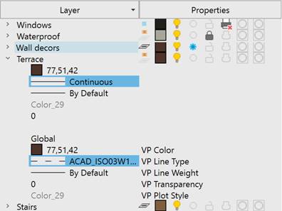
When working in paper space and with a current paper viewport, columns with information about the parameters of layers in the current viewport are added to the layer list table:
|
|
Displays the icon of the layer freeze in the current viewport. |
|
VP Color |
Displays the layer’s color in the current viewport. |
|
VP Line Type |
Displays the layer’s linetype in the current viewport. |
|
VP Line Weight |
Displays the layer’s line weight in the current viewport. |
|
VP Transparency |
Displays the layer’s transparency in the current viewport. |
|
VP Plot Style |
Displays the layer’s plot style in the current viewport. |

Double-clicking the left mouse button on the column title separator automatically changes the width of columns:

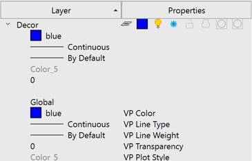
Tree view of the list of layers
In the tree view, the left column displays the names of the layers, and the right one displays the properties.
The Properties column displays the following options: Status, Color (VP Color), Layer Visibility, Frozen, Locked, Plot, New VP Freeze, VP Freeze.
The remaining parameters are expanded as a list under the layer name when you left-click on the arrow to the left of the layer name:
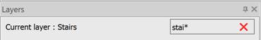
To quickly search for layers by name, use the Search for layer field in the upper right part of the dialog.
To search for layers by name:
4. Enter the layer’s name or part of the name in the field to search.
As you type, only those elements whose names contain the entered expression remain in the list of layers. You can use special characters in the field, as described in the Search Field section.
Creating a New Layer
A newly created layer has properties set by default (the same as layer 0). If you select a layer before clicking the button, the properties of that layer will be used by default for the new layer. After creating a new layer, its properties can be modified.
To create a new layer:
5. Click the  Add button.
To create a new layer frozen in all viewports:
6. Click the  Add Layer VP Frozen in All Viewports button. A layer frozen in all viewports will have the
  icon next to its name in the VP Freeze column.
A new layer is added to the list of layers with the default name LayerN, where N is the sequential number of the created layer, starting from 1. The name assigned to the created layer by default can be changed. The name should contain at least one character. Layer names should not be duplicated. Invalid characters for a layer name: < > / \ “ ” : ; ? * | , = ` tab character.
A new layer can be also created by the context menu command Add or Add Layer VP Frozen in All Viewports.
Deleting a Layer
Layers that are not used in the document can be deleted. The current layer, even if it is not used in the document, cannot be deleted. You can remove several layers at once.
To delete a layer:
7. Select one or more layers in the list.
8. Click the  Delete dialog button
A layer can also be deleted using the Delete context menu command.
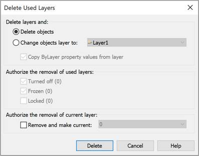
When deleting used layers that contain objects, the Delete command opens the Delete Used Layers dialog box to select deletion options:
|
Delete layers and: |
Selects an action with objects of the layer to be deleted. |
|
Delete objects |
Deletes the selected layer with all objects on it. |
|
Change objects layer to |
Moves objects of the layer being deleted. You can move objects to an automatically created new layer LayerN or select an existing layer from the list. |
|
Copy ByLayer property values from layer |
Saves the By Layer property values for objects being moved. |
|
Authorize the removal of used layers: |
Sets permission to delete layers with certain properties: Turned off, Frozen, Locked. These options are only available if the layers to be deleted contain these properties. The number of selected layers with this property is displayed in brackets. |
|
Authorize the removal of current layer |
Sets permission to delete the current layer. |
|
Remove and make current |
Selects the current layer from the list when deleting a previously installed one. |
9. After setting the parameters, click the Delete dialog button.
If there are layers in the selection for deletion that cannot be deleted, information about them (layer name and reason) is displayed in the Delete Layers dialog:
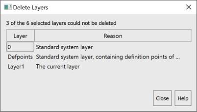
note You can delete the Defpoints standard system layer using the LAYDEL command.
View mode for selected layers (layer walk)
In the selected layers view mode, the visibility of all layers except the selected ones is turned off, and when exiting the mode, it is restored to its previous position. This mode is convenient to use when there are a large number of layers in the drawing.
To view one or more selected layers:
10. Select one or more layers in the list with the left mouse button.
11. Enable the  Layer Walk button, in this case the visibility of all layers except the selected ones will be temporarily disabled. The icon is displayed next to the selected layers in the
  column, indicating that these layers are visible in the drawing.
12. You can add other layers for viewing by left-clicking on the  icon in the column (the icon changes to ).
13. Left-clicking on the icon turns off the layer visibility (the icon changes to ).
To exit the view mode for selected layers:
14. Disable the  Layer Walk button.
The visibility of all turned off layers will be restored.
Layer Settings
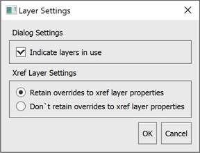
To manage the display parameters of layers and the layer properties included in external references, use the Layer Settings dialog, which is opened by clicking the  button.
|
Dialog options: |
|
|
Indicate layers in use |
Whether or not to mark unused layers in the list of layers. The status of the used layers does not depend on the option. The status of an unused layer when the option is enabled will look like this: |
|
Xref Layer Settings: |
|
|
Retain/Don’t retain overrides to xref layer properties |
Whether or not changes to the parameters of layers included in external references are retained. |
 ,
,  ,
, The list of layers can be sorted by any parameter. To sort the list of layers by any parameter, just left-click on its column header.
The sorting direction is indicated by an arrow in the header of the sorted parameter.


Editing Layer Parameters
Selecting layers from the list
A layer is selected by clicking on it with the left mouse button.
You can edit the parameters of several selected layers at once.
Holding down the SHIFT key selects all layers located between the first and last mouse click.
By holding down the CTRL key, you can add any layer from the list to the existing selection of layers by clicking the mouse.
All layers in the list are selected using the Select All context menu command. The Unselect All command deselects all selected layers in the list.
Renaming a Layer
The following layers cannot be renamed: Layer 0 and layers that depend on xrefs.
To rename a layer:
15. Select a layer in the list.
16. Left-click on the layer name or press the F2 key.
17. Enter a new layer name.
18. Press ENTER.
A layer can also be renamed using the Rename context menu command.
To set a layer current:
19. Left-click in the icon display column opposite the name of the selected layer. The  icon will be located opposite the selected layer, which indicates that this layer is the current one.
The current layer can also be selected using the Set Current context menu command.
Assigning Properties to a Layer
A layer can be assigned such properties as Color, Linetype, Lineweight, Transparency, Description and Covering, which will be inherited by all objects on that layer if these object properties are set to By Layer.
To assign Color, Linetype, Lineweight, Transparency, Description and Covering for one layer in a tree view of the list of layers:
20. Open the layer parameters by left-clicking on the arrow to the left of the layer name.
21. Left-click on the desired parameter.
22. Select the required parameter value from the drop-down list. For the Explanation property, in the Place for description... field, enter the explanatory text.
Color, Linetype, Lineweight, Transparency, Description and Covering can be set for several layers at once:
23. Change the presentation of layers to table view format using the  button.
24. Select one or more layers in the list.
25. Left-click in the column of the desired property of one of the selected layers.
26. Select the required parameter value from the drop-down list. For the Explanation column, enter the explanatory text in the Place for description... field.
The description can also be changed using the Change Description context menu command.
Managing a Layer Visibility
Objects located on turned off layers are not displayed on the screen and are not printed, but take part in the drawing regeneration. However, when turning layers on/off, the drawing does not regenerate. In this regard, it is recommended to turn layers on/off in cases where this needs to be done frequently and when layers are turned off for a short time. Otherwise, it is better to freeze the layers.
Visible layers are indicated by the  icon. The icon indicates that the visibility of this layer is turned off.
You can turn visibility on and off for several layers at once.
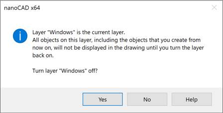
When you turn off the visibility of the current layer, a warning window appears.
To turn on/off a layer visibility:
27. Select one or more layers in the list.
28. Left-click in the column that displays the () icon next to the name of one of the selected layers.
note You can manage the visibility of drawing objects not only by switching the visibility of the layer they lie on, but also directly using the commands for hiding and isolating objects.
Freezing a Layer
Objects located on frozen layers are not displayed on the screen, are not printed, and do not participate in drawing regeneration. Freezing unnecessary layers in large drawings can accelerate displaying and regenerating operations. However, the operation of thawing one or more layers leads to the drawing regeneration, which takes quite a long time. In this regard, layers should be frozen in cases where it is rarely necessary and when layers are frozen for a long time. Otherwise, it is better to turn off the visibility of layers.
Frozen layers are indicated by the  icon, and thawed ones by
  .
.
You can freeze and thaw several layers at once. You cannot freeze the current (  ) layer.
To freeze/thaw a layer:
29. Select one or more layers in the list.
30. Left-click in the column that displays the () icon next to the name of one of the selected layers.
Freezing Layers in Layout Viewports
Layers can be frozen in individual layout viewports. This way, you can get different displays of the same objects in different viewports without creating additional (duplicate) geometry, for example, by creating two viewports for the same object and freezing the layer with design elements in the second viewport.
Layers frozen in the current viewport are indicated by the  icon.
icon.
The section of Managing Frozen Layers in Individual Viewports describes the VPLAYER command in detail.
To freeze a layer in the current viewport:
31. Activate the viewport by double-clicking on it with the left mouse button.
32. In the list of layers, select all layers to be frozen in the current viewport.
33. Freeze the selected layers by clicking on the  icon for any selected layer.
The layer will be frozen only in this viewport and visible in all others. When printing a layout, the frozen layer will also not be plotted in just that one viewport.
To freeze a layer in all VPs:
1. In the list of layers, select all layers that should be frozen in all viewports.
2. Right-click on the selected layers to open the context menu and select the VP Freeze Layer > In All Viewports command.
The layers will be frozen and invisible in all viewports.
To freeze a layer on all VPs except the current one:
1. Activate the viewport by double-clicking on it with the left mouse button.
2. In the list of layers, select all layers that should be frozen in all viewports except the current one.
3. Right-click on the selected layers to open the context menu and select the VP Freeze Layer > In All Viewports Except Current command.
The layers will be frozen and invisible in all viewports except the current one.
You can also use the LAYVPI command to freeze a layer in all layout viewports except the current one.
To thaw a layer in all VPs:
1. In the list of layers, select all layers to be thawed in all viewports.
2. Right-click on the selected layers to open the context menu and select the VP Thaw Layer in All Viewports command.
The layers will be thawed and visible in all viewports of all layouts.
Overriding Layer Properties in Viewports
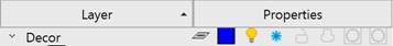
Layer property override is a way to display objects in different layout viewports with different property values (color, linetype and lineweight, transparency) without changing the properties that are assigned with ByLayer or ByBlock values.
To override properties for the current layout viewport in a tree view of the list of layers:
3. Activate the viewport by double-clicking on it with the left mouse button.
4. Open the layer parameters by left-clicking on the arrow to the left of the layer name.
5. Left-click on the desired property: VP Color, VP Linetype, VP Lineweight or VP Transparency.
6. Select a value from the drop-down list.
To override properties for the current layout viewport for multiple layers:
7. Change the presentation of layers to table format using the button.
8. Select one or more layers in the list.
9. Left-click in the property column (VP Color, VP Linetype, VP Lineweight or VP Transparency) of one of the selected layers.
10. Select a value from the drop-down list.
The parameters will be changed only in that layout viewport. In other viewports and in Model space, these parameters will remain unchanged.
Layers that have property overrides in viewports are highlighted in blue and the status indicator for such layers has changed:
Removing Viewport Layer Property Overrides
To cancel overrides of layer properties in viewports, use the Remove Viewport Overrides for context menu command.
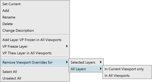
Command options:
|
Selected Layers |
Removes property overrides for selected layers. Removal can be made: In Current Viewport only In All Viewports. |
|
All Layers |
Removes property overrides in all layers. Removal can be made: In Current Viewport only In All Viewports. |
Locking a Layer to Make Changes
Objects located on locked layers are displayed on the screen, but they cannot be edited. You can create new objects on a locked layer. For a locked layer, you can change the color, linetype and lineweight, and allow or disallow its printing.
Locked layers are indicated by the  icon, and unlocked layers are indicated by the
  icon.
icon.
You can lock and unlock several layers at once.
To lock/unlock a layer:
11. Select one or more layers in the list.
12. Left-click in the column that displays the () icon next to the name of one of the selected layers.
There is a mode for enabling the selection of objects on locked layers to view their properties and use object snap.
To be able to select objects on locked layers:
In the status bar, enable the  Select objects on locked layers button.
Managing Layer Availability for Plotting
The  icon displayed as an outline indicates that objects located on the layer will be plotted. Objects on layers marked with the
  icon will not be plotted.
You can enable or disable printing for several layers at once.
To prohibit/allow a layer to be plotted:
13. Select one or more layers in the list.
14. Left-click in the column that displays the () icon next to the name of one of the selected layers.