
 De
De  Es
Es  Fr
Fr 

-
-
-
-
-
-
-
-
-
-
-
-
-
-
-
-
-
-
-
-
-
-
-
-
-
-
-
Correction by Histogram
-
-
-
-
-
-
-
-
-
-
-
-
-
-
-
-
-
-
-
-
-
-
-
-
-
-
-
-
-
Correction by Histogram
 Ribbon: Raster – Processing >
  Equalize
 Menu: Raster – Processing the raster > Equalize…
 Command line: Equalizer
 This functionality is available only in the Raster module.
The operation is used to adjust the brightness, color hue and contrast of an image. To do this, a histogram correction algorithm is used with the setting of two threshold brightness levels - the darkest and brightest pixels, as well as the image gamma, which determines the position of the average brightness value relative to the current threshold values.
Gamma specifies the ratio of length of the brightness range between the average and the brightest values to the length of the brightness range between the dark threshold and the average value. As a result of using the command:
· pixels with a brightness value below the dark threshold receive a zero brightness value;
· pixels with brightness values higher than the brightest - maximum brightness value (255);
· the brightness values of pixels lying between the darkest and average values and between the average and the brightest levels are redistributed evenly in accordance with the lengths of the intervals given to them, which are determined by the image gamma.
Increasing the gamma value decreases the interval provided for brightness in the dark range and therefore increases the contrast in it, while simultaneously decreasing the contrast in the light range, and vice versa.
The command allows you to redistribute both the average brightness of the image pixels and the brightness by individual color components of pixels (Red, Green and Blue). This allows you to correct the color of pixels in the image - for example, make a pink background pure white.
1. Select raster images to be processed.
2. Run the command.
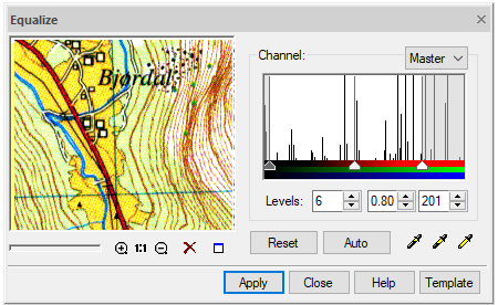
The Equalize dialog box presents the image histogram that shows the averaged number of pixels corresponding to each brightness value:
· low brightness values correspond to the left side of the histogram;
· high (lightest tones) - the right side of the histogram.
The slides at the bottom of the histogram show the threshold values: black on the left is the darkest, gray in the middle is the average, and white on the right is the brightest pixel.
It is possible to choose one of four histograms:
· Master shows the summarized distribution of pixel brightness;
· Red, Green and Blue show the brightness distribution of the corresponding color components of pixels (red, green, and blue).
Select the histogram corresponding to the color component to be corrected.
Set the brightness values of the darkest, lightest pixel and gamma of the image using the Levels fields or the eyedropper. For fine tuning, use the histogram sliders.
The Levels fields contain a numerical expression of the current thresholds. Using the sliders of the Master histogram, you can proportionally change the values of the thresholds of all components at the same time. The Red, Green, and Blue histogram sliders change the brightness thresholds separately for their respective color components. The eyedroppers are used to select thresholds and gamma in an image. If a color sample is taken by an eyedropper  Pick low level (or
  Pick high level), then the value of the darkest (brightest) threshold component is set. If a color sample is taken by an eyedropper
  Pick middle level, the middle tone position is defined and thereby – the image gamma. The brightness values of all other pixels will be proportionally redefined within the boundaries of the new tone range. Moving the middle slider changes the gamma value and redistributes the contrast between the light and dark parts of the image.
The Auto button automatically sets the values of the light and dark thresholds so as to cut off the brightness values for each color component that are not found in the image.
Click Apply to perform the operation.
This correction can be performed repeatedly by sequentially changing the brightness distribution of the image pixels.