
 De
De 

-
-
-
-
-
-
-
-
-
-
-
-
-
-
-
-
-
-
-
-
-
-
-
-
-
-
-
-
-
-
-
-
-
Interface of the Table Editor Dialog
-
-
-
-
-
-
-
-
-
-
-
-
-
-
-
-
-
-
-
-
-
Interface of the Table Editor Dialog
The full table editor (the Table edit dialog box) when the Program objects parameter is set to Yes in the Edit – By double-click section of the Main options tab of the nanoCAD Design Settings (PARAMS) dialog box, can be opened:
· by double-clicking on the frame inserted into the drawing table,
· by right button clicking on the table frame (the full table editor will be opened if you press CTRL).
The edit and fedit commands allow you to open the Table edit dialog box, it does not matter what value is chosen for the Program objects option.
You can also open the Table edit dialog by selecting the table, clicking the right button and selecting the Edit command in the context menu.
The Table edit dialog box:
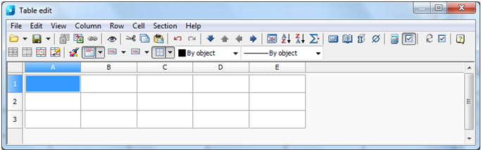
The dialog box contains:
· standard pull-down menus
 ;
;
· tool palette buttons

· rulers with sliders allowing column width or row height to be quickly adjusted
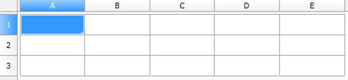
· the cell grid with name headers
 .
.
· status bar with transparency and scale sliders.
Each table section has a header:
· First page header
· Header
· Last page header
· Report header
· Report template
· Report
· Report sum
· First page footer
· Footer
· Last page footer
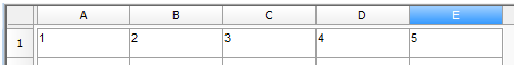
Click the left mouse button on a row or column name to select it.
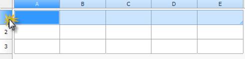
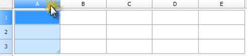
To select the table, click the rectangle at the intersection of the lines and columns names:
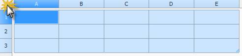
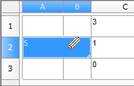
Names (addresses) of table cells are fully equivalent to those used in MS Excel: columns are marked alphabetically (A, B, C, D, ... , Z; AA, BB etc.) while rows are marked with ordinal numbers.
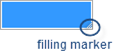
Filling of adjacent cells with data
To accelerate the data input in the table, it is possible to use the function of automatic data filling. The table editor can automatically continue a line of numbers, number combinations and text with a set pattern. By selecting several cells and dragging the filling marker, it is possible to quickly fill in the data lines with the different types.
Filling cells with sequences of numbers or combinations of numbers and text with a set pattern:
For example: Filling cells with sequences of 1, 2, 3, 4, 5 numbers.
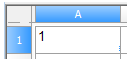
1. Select the first of the filled cells:
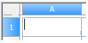
2. Enter the initial value for the values line:
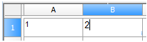
3. Enter a value in the following cell to set the filling pattern:
4. Select the cell or cells containing the initial values:
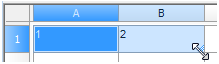
5. Drag the filling marker over the range with which it is necessary to fill:
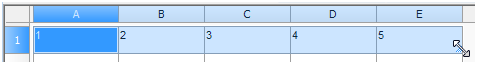
6. The cells will be filled with the set sequence of numbers:
Examples:
1. If the sequence 2, 4, 6, 8… is required, enter 2 and 4.
2. If the sequence 2, 2, 2, 2… is required, the second cell can be left empty.
3. The sequence filling proceeds as shown in the table below:
|
Initial value |
Line extension |
|
1, 2, 3, ... |
4, 5, 6, ... |
|
First period, Second period, … |
Third period... |
|
Article 1, Article 2, … |
Article 3... |
Note! To fill in an increasing order, drag the marker down or to the right. To fill in a decreasing order, drag the marker up or to the left.
Use the autofilling to continue lists containing the values from collections (main menu/rows/user sorting).
|
|
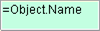
Cell containing an expression. |
|
|
Not edited cell, for example, in report. |
|
|
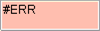
Cell with a mistake in expression. |
|
|
Cell containing data of report section. |

The files tools:
|
|
Open table: |
Allows a data set from a previously created *.dat file to be imported, or a standard table template from the nanoCAD library to be imported. Clicking the black triangle shows additional buttons which are used to select the data source:
If the Excel file is chosen, only the first list will be inserted. |
|
|
Save to file: |
Exports the cell data to a special *.dat file format, or saves it in the nanoCAD library. Clicking the black triangle shows additional buttons used to select the desired destination:
|
|
|
Export to Excel: |
Exports the table data to MS Excel. Clicking this button creates a new Excel worksheet containing all the table data with identical formatting. |
|
|
Import from Excel: |
Imports calculated data from an open MS Excel worksheet. |


 - Insert a table from the library.
 - Insert a table from an external file *.tbl, *.dat, *.mdb, *.txt, *.csv, *.xml, *.xls, *.xlsx.

 - Save table in nanoCAD library.
 - Export table to an external file *.dat, *.txt, *.csv, *.xml, *.xls.

The standard windows clipboard tools:
|
|
Cut: |
Copy the selected data into the clipboard and delete from the table. |
|
|
Copy: |
Copy the selected data into the clipboard. |
|
|
Paste: |
Paste data from the clipboard. |


Undo and redo last change tools:
|
|
Undo last change: |
Undo last change. |
|
|
Redo last change: |
Redo last change. |


Formatted cell navigation tools:
|
|
Move row down: |
Moves the selected row one position down. |
|
|
Move row up: |
Moves the selected row one position up. |
|
|
Move column left: |
Moves the selected column one position left. |
|
|
Move column right: |
Moves the selected column one position right. |
|
|
Page division: |
This tool is intended for dividing a table into multiple fragments without losing its integrity. Use this function to split a large table in order to place it on a smaller sheet of paper, while still being able to edit it as a whole. |


Tools used for sorting cells by contents:
|
|
Sort ascend: |
Sorts rows in ascending order of cell values in the current column (column of the selected cell). |
|
|
Sort descend: |
Sorts rows in descending order of cell values in the current column (column of the selected cell). |


Other tools:
|
|
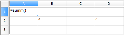
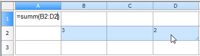
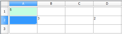
Create summary function: |
Summarises the contents of the chosen cells: · Select the cell in which it is required to calculate the sum. · Click the button
· Select the cells which are to be summarised:
· Press Enter:
|
|
|
Open calculator: |
Opens the Calculator window. |
|
|
Open Notepad: |
Opens the Notepad window. |
|
|
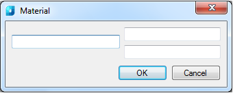
Insert material: |
Use this tool to insert formatted rows of material into the table. Click the icon to open the Material dialog box:
|
|
|
Special Symbols: |
Allows a special symbol to be inserted from the menu. |
|
|
Recalculate Table: |
This button is used to manually update the calculated cell data after editing reference cell values or altering expressions. |
|
|
Automatic calculation: |
Operates a mode of automatic recalculation of the values of the table cells. By default, the automatic calculation mode is included. |
|
|
Update reports: |
Click this button to update the report. |
|
|
Automatic report update: |
Operates a mode of automatic recalculation of the report. By default, the automatic report update mode is included. |


Tools to work with the cells:
|
|
Group selection: |
Merges multiple cells into a single cell. |
|
|
Ungroup selected cells: |
Restores the original cells from merged cells. |
|
|
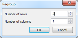
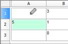
Change count of rows and columns: |
Use to change the count of rows and (or) columns in the chosen cells range: · Select one or several cells. · Click the Change count of rows and columns button. · In the Regroup dialog box that appears, enter the required values for breakdown
|
|
|
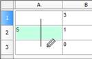
Split table cells with pencil tool |
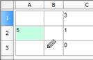
Use to insert new cells by manually drawing new grid lines: · Specify the start and end point of a line which will divide each cell that is crossed by it into two:
· Right-click on a cell border to delete this border:
· Click Split table cells with pencil tool button to finish. |


Text alignment tools
|
|
Text alignment |
Use to control the text alignment in the selected cells. Clicking the black triangle brings up additional buttons:
The remaining tool icons are self-explanatory. |


Management tools of cell borders display
|
|
Borders: |
Use to display or hide the borders of the selected cells. Clicking the black triangle brings up additional buttons used to toggle border visibility:
The remaining tool icons are self-explanatory. |
|
|
Border Color: |
To set the border parameters: · It is necessary to select again the color or lineweight. · Choose the border (use the Borders |
|
|
Border Lineweight: |


 - No border lines.
 - Display all lines around the selected cells.
 - Display all borders - inner and outer.
 command) to which it is necessary to apply the set parameters.
The parameters of table cells are set in the Cell properties dialog box:
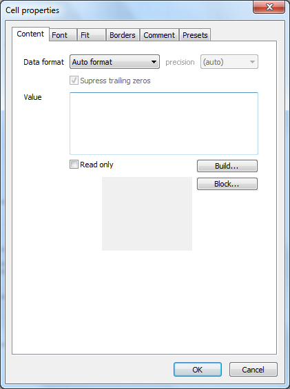
To edit the properties of a cell:
1. Select the required cell in the Table edit dialog box.
2. Select the Properties command from the right-button menu or use the Ctrl + Enter key combination or double click on the cell.
3. Set necessary properties in the Cell Properties dialog box.
Note: The action of this command is similar to Cell Properties on the Table edit toolbar.
To edit several table cells:
1. Select the required cells.
2. Select the Properties command from the right-button menu or use the Ctrl + Enter key combination or double click on the cell.
3. Set necessary properties in the Cell Properties dialog box.
note: The effect of this command is similar to Cells Properties on the Table edit toolbar.