De
De  Es
Es  Fr
Fr 

2D Constraints
 .
.
Geometric constraints allow you to create dependent geometry.
1. Call command  "Geometric constraints".
|
|
Also, each dependency has its own call command. |
2. Select the required geometric dependence from the context menu or from the command line:
· Vertical
· Parallel
· Tangent
· Smooth
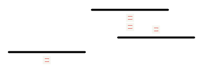
· Equal
· Fix
3. Take the necessary action.
4. Constraint will be installed.

 .
.
.
.
.
The command imposes a dependency overlap.
1. Call command "Coincident".
|
|
After the command is called, other dependency commands will be available in the context menu, which you can switch to if necessary. The list of dependencies is controlled by the switch "Continuous add of constraints in manual mode (autoadd until interrupted)". |
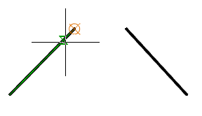
2. Specify the first base point of the object or select the object.
To select a point, you must hover over the object. The selected point will be shown in orange. To select the desired point, you must hover over the object from the desired side. To select a point, press LMB. The selected point turns green.
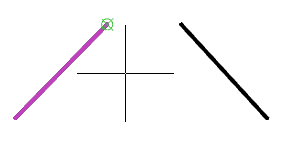
To select an object, select the "O-object" command in the context menu and select the required object. The subsequent selected point will be related to it collinearly.
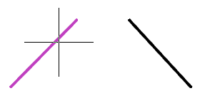
3. Select the point of the second object in the same way as the first. There will be a combination. The alignment point will be displayed in a yellow square.
If two points were chosen, then they will be combined. The second point moves to the point selected first.
If an object and a point were selected, the second object will be placed in such a way that the point is collinear to the first object.
|
|
If the switch is on "Continuous add of constraints in manual mode (autoadd until interrupted)", after applying the dependency, the system will automatically switch to the insertion of the following dependency. To exit the loop, press "Esc". |
Allowable objects and dependency points
· control points of objects;
· line segment;
· circle;
· arc;
· segment of a polyline (rectilinear or arc);
· ellipse.
 .
.
.
.
.
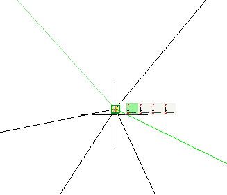
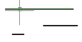
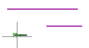
The command imparts collinearity to objects.
1. Call command "Collinear".
|
|
After the command is called, other dependency commands will be available in the context menu, which you can switch to if necessary. The list of dependencies is controlled by the switch "Continuous add of constraints in manual mode (autoadd until interrupted)". |
2. Specify the first object, or select the command "M-multiple" from the context menu, which allows you to assign a dependency to several objects at once.
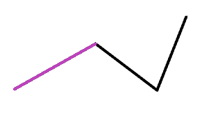
3. Specify the second object and subsequent objects (if the "M-multiple" command was selected).
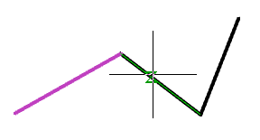
4. Objects will be collinear, that is, they will be located on the same line. Near the objects there will appear icons of superimposed dependencies.
|
|
If the switch is on "Continuous add of constraints in manual mode (autoadd until interrupted)", after applying the dependency, the system will automatically switch to the insertion of the following dependency. To exit the loop, press "Esc". |
Allowable objects and dependency points
· line segment;
· rectilinear segment of a polyline.
 .
.
.
.
.
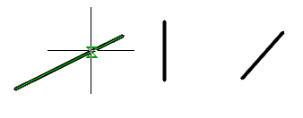
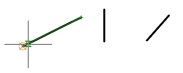
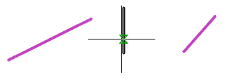
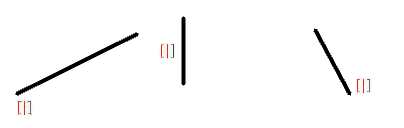
The command superimposes verticality on objects.
1. Call command "Vertical".
|
|
After the command is called, other dependency commands will be available in the context menu, which you can switch to if necessary. The list of dependencies is controlled by the switch "Continuous add of constraints in manual mode (autoadd until interrupted)". |
2. Determine how to apply the dependency: to an object or to a control point. In order to impose a dependency on the control point, call the context menu command "2-2 points".
3. Select an object or points (depending on the selected method). Points can belong to different objects.
|
Object |
2 points |
|
|
|
4. Dependence will be imposed. Near the objects there will appear icons of superimposed dependencies.
|
Object |
2 points |
|
|
|
|
|
If the switch is on "Continuous add of constraints in manual mode (autoadd until interrupted)", after applying the dependency, the system will automatically switch to the insertion of the following dependency. To exit the loop, press "Esc". |
Allowable objects and dependency points
· control points of objects;
· line segment;
· rectilinear segment of a polyline.
 .
.
.
.
.
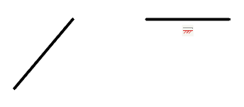
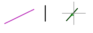
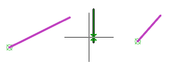
The command superimposes horizontality on objects.
1. Call command "Horizontal".
|
|
After the command is called, other dependency commands will be available in the context menu, which you can switch to if necessary. The list of dependencies is controlled by the switch "Continuous add of constraints in manual mode (autoadd until interrupted)". |
2. Determine how to apply the dependency: to an object or to a control point. In order to impose a dependency on the control point, call the context menu command "2-2 points".
3. Select an object or points (depending on the selected method). Points can belong to different objects.
|
Object |
2 points |
|
|
|
4. Dependence will be imposed. Near the objects there will appear icons of superimposed dependencies.
|
Object |
2 points |
|
|
|
|
|
If the switch is on "Continuous add of constraints in manual mode (autoadd until interrupted)", after applying the dependency, the system will automatically switch to the insertion of the following dependency. To exit the loop, press "Esc". |
Allowable objects and dependency points
· control points of objects;
· line segment;
· rectilinear segment of a polyline.
 .
.
.
.
.
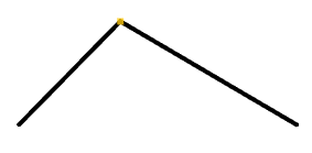
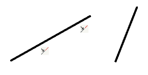
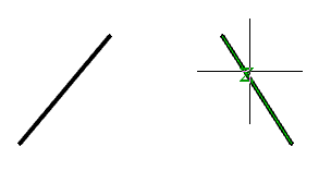
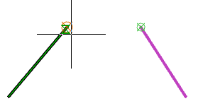
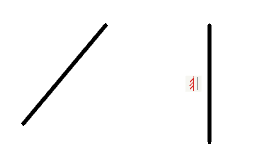
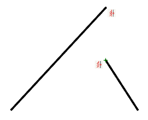
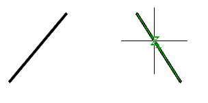
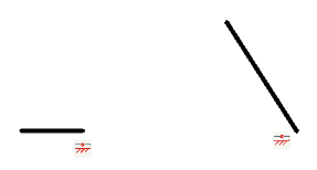
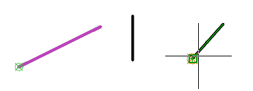
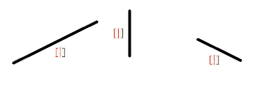
The command imposes a perpendicularity on the objects.
1. Call command "Perpendicular".
|
|
After the command is called, other dependency commands will be available in the context menu, which you can switch to if necessary. The list of dependencies is controlled by the switch "Continuous add of constraints in manual mode (autoadd until interrupted)". |
2. Select the first object.
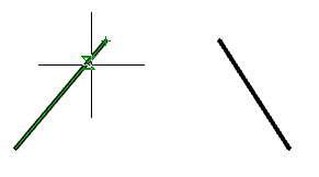
3. Select the second object.
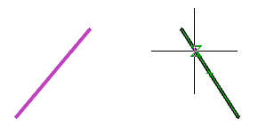
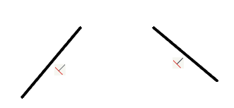
4. Constraint will be imposed. Objects will become perpendicular to each other. Near the objects there will appear icons of superimposed dependencies.
|
|
If the switch is on "Continuous add of constraints in manual mode (autoadd until interrupted)", after applying the dependency, the system will automatically switch to the insertion of the following dependency. To exit the loop, press "Esc". |
Allowable objects and dependency points
· line segment;
· rectilinear segment of a polyline.
 .
.
.
.
.
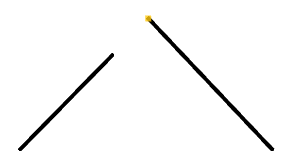
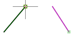
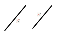
he command imposes a parallel dependency on objects.
1. Call command "Parallel".
|
|
After the command is called, other dependency commands will be available in the context menu, which you can switch to if necessary. The list of dependencies is controlled by the switch "Continuous add of constraints in manual mode (autoadd until interrupted)". |
2. Select the first object.
3. Select the second object.
4. Dependence will be imposed. Objects will become parallel to each other. Near the objects there will appear icons of superimposed dependencies.
|
|
If the switch is on "Continuous add of constraints in manual mode", after applying the dependency, the system will automatically switch to the insertion of the following dependency. To exit the loop, press "Esc". |
Allowable objects and dependency points
· line segment;
· rectilinear segment of a polyline.
 .
.
.
.
.
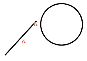
The command superimposes the touch dependence on objects.
1. Call command "Tangent".
|
|
After the command is called, other dependency commands will be available in the context menu, which you can switch to if necessary. The list of dependencies is controlled by the switch "Continuous add of constraints in manual mode". |
2. Select the first object. One of the selectable objects should be: a circle, an arc, an arc segment of a polyline, an ellipse.
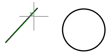
3. Select the second object. One of the selectable objects should be: a circle, an arc, an arc segment of a polyline, an ellipse.
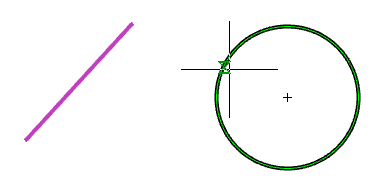
4. Dependence will be imposed. Objects will touch each other. Near the objects there will appear icons of superimposed dependencies.
|
|
If the switch is on "Continuous add of constraints in manual mode", after applying the dependency, the system will automatically switch to the insertion of the following dependency. To exit the loop, press "Esc". |
Allowable objects and dependency points
· line segment;
· rectilinear segment of a polyline;
· circle, arc, arc segment of a polyline, ellipse;
· combinations of circles, arcs, arc segments of polylines, ellipses.
 .
.
.
.
.
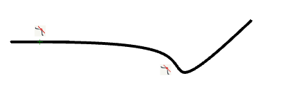
The command imposes the smooth constraint on a spline and object.
1. Call command "Smooth".
|
|
After the command is called, other dependency commands will be available in the context menu, which you can switch to if necessary. The list of dependencies is controlled by the switch "Continuous add of constraints in manual mode". |
2. Select a point on the first curve.
|
|
The first curve should always be a spline! |
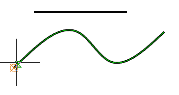
3. Select a point on the second curve.
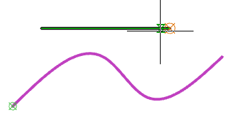
4. Dependence will be imposed. Near the objects there will appear icons of superimposed dependencies.
|
|
If the switch is on "Continuous add of constraints in manual mode", after applying the dependency, the system will automatically switch to the insertion of the following dependency. To exit the loop, press "Esc". |
Allowable objects and dependency points
· spline;
· line segment;
· rectilinear and arc segment of the polyline;
· arc.
 .
.
.
.
.
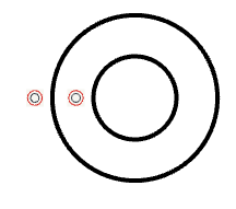
Command constraint on the alignment of circles, arcs and other objects.
1. Call command "Concentric".
|
|
After the command is called, other dependency commands will be available in the context menu, which you can switch to if necessary. The list of dependencies is controlled by the switch "Continuous add of constraints in manual mode". |
2. Select the first object.
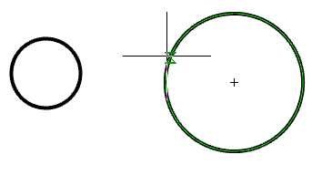
3. Select the second object.
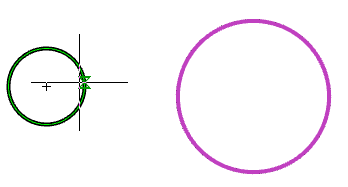
4. Dependence will be imposed. Near the objects there will appear icons of superimposed dependencies.
|
|
If the switch is on "Continuous add of constraints in manual mode", after applying the dependency, the system will automatically switch to the insertion of the following dependency. To exit the loop, press "Esc". |
Allowable objects and dependency points
· circle;
· arc;
· arc segment of a polyline;
· ellipse.
 .
.
.
.
.
The command sets the relationship between the equality of dimensions (length, diameter, radius, etc.) of two or more objects.
1. Call command "Equal".
|
|
After the command is called, other dependency commands will be available in the context menu, which you can switch to if necessary. The list of dependencies is controlled by the switch "Continuous add of constraints in manual mode". |
2. Specify the first object, or select the command "M-multiple" from the context menu, which allows you to assign a dependency to several objects at once.
3. Specify the second object and subsequent objects (if the "M-multiple" command has been selected).
4. Dependence will be imposed. Near the objects there will appear icons of superimposed dependencies.
|
|
If the switch is on "Continuous add of constraints in manual mode", after applying the dependency, the system will automatically switch to the insertion of the following dependency. To exit the loop, press "Esc". |
Allowable objects and dependency points
· line segment;
· rectilinear and arc segment of the polyline;
· circle;
· arc.
 .
.
.
.
.
The command sets the symmetry of the two objects relative to the axis of symmetry (line).
1. Call command "Symmetric".
|
|
After the command is called, other dependency commands will be available in the context menu, which you can switch to if necessary. The list of dependencies is controlled by the switch "Continuous add of constraints in manual mode". |
2. Determine how to apply the dependency: to an object or to a control point. In order to impose a dependency on the control point, call the context menu command "2-2 points".
3. Select the first object or point (depending on the selected method). Points can belong to different objects.
|
Object |
2 points |
|
|
|
4. Select the second object or point (depending on the selected method). Points can belong to different objects.
|
Object |
2 points |
|
|
|
5. Select the axis of symmetry.
|
|
The axis of symmetry must be a line. |
|
Object |
2 points |
|
|
|
6. Dependence will be imposed. Near the objects there will appear icons of superimposed dependencies.
|
Object |
2 points |
|
|
|
|
|
If the switch is on "Continuous add of constraints in manual mode", after applying the dependency, the system will automatically switch to the insertion of the following dependency. To exit the loop, press "Esc". |
Allowable objects and dependency points
· line segment;
· rectilinear and arc segment of the polyline;
· circle;
· arc;
· ellipse.
 .
.
.
.
.
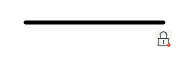
The command captures a point or object in current coordinates.
1. Call command "Fix".
|
|
After the command is called, other dependency commands will be available in the context menu, which you can switch to if necessary. The list of dependencies is controlled by the switch "Continuous add of constraints in manual mode". |
2. Determine how to add a dependency: to a control point or to an object. To impose a dependency on an object, call the command of the context menu "O-object".
3. Select an object or a point (depending on the selected method).
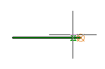
4. Dependence will be imposed. Near the objects there will appear icons of superimposed dependencies.
|
|
If the switch is on "Continuous add of constraints in manual mode", after applying the dependency, the system will automatically switch to the insertion of the following dependency. To exit the loop, press "Esc". |
Allowable objects and dependency points
· line segment;
· rectilinear and arc segment of the polyline;
· arc;
· circle;
· ellipse;
· spline.
 .
.
.
.
.
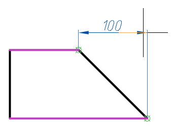
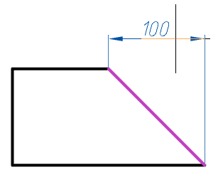
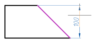
The command sets the dimensional constraint to apply parallel dimensions.
1. Call command "Aligned".
|
|
After the command is called, other dependency commands will be available in the context menu, which you can switch to if necessary. The list of dependencies is controlled by the switch "Continuous add of constraints in manual mode". |
2. Determine how to insert an equalized size: 2 points (by default when the command is called), O-object, P-point_line, 2-2lines. The method of insertion is determined by selecting the appropriate command from the context menu.
· 2 points - sets the parallel dimension to two points.
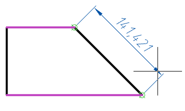
· O-object - sets the parallel size for the selected object.
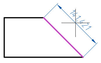
· P-point_line - sets the size that is parallel to the normal from the selected point to the selected segment.
· 2-2lines - sets the size parallel to the normal between two segments.
3. Specify the required objects, depending on the selected insertion method.
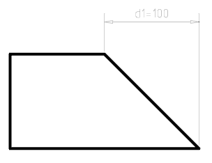
4. Place the parametric dimension on the drawing.
5. Parametric size will be built and added to the "Parameters Manager". A variable is assigned to the parameter dimension.
|
|
If the switch is on "Continuous add of constraints in manual mode", after applying the dependency, the system will automatically switch to the insertion of the following dependency. To exit the loop, press "Esc". |
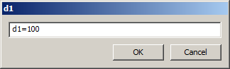
To edit the parametric size, double-click on the size. An editing dialog opens, where you can change the name of the variable and the value. The value can be a formula.
Also, the parametric size can be edited in "Parameters Manager".
Allowable objects and dependency points
· control points of objects;
· line segment;
· arc;
· segment and control point;
· two segments;
· segment of a polyline (rectilinear or arc).
 .
.
.
.
.
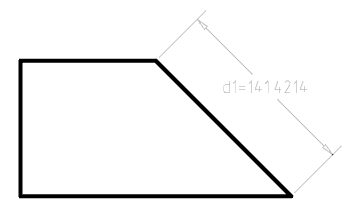
The command sets the linear dimension relationship. The linear dimension is constructed orthogonally to the coordinate system.
1. Call command "Linear".
|
|
After the command is called, other dependency commands will be available in the context menu, which you can switch to if necessary. The list of dependencies is controlled by the switch "Continuous add of constraints in manual mode". |
2. Determine how to insert an equalized size: 2 points (by default when the command is called) or O-object. The method of insertion is determined by selecting the appropriate command from the context menu.
· 2 points - sets the orthogonal size by two points.
· O-object - sets the orthogonal size for the selected object.
3. Specify the required objects, depending on the selected insertion method.
4. Place the parametric dimension on the drawing.
5. Parametric size will be built and added to the "Parameters Manager". A variable is assigned to the parameter dimension.
|
|
If the switch is on "Continuous add of constraints in manual mode", after applying the dependency, the system will automatically switch to the insertion of the following dependency. To exit the loop, press "Esc". |
To edit the parametric size, double-click on the size. An editing dialog opens, where you can change the name of the variable and the value. The value can be a formula.
Also, the parametric size can be edited in "Parameters Manager".
Allowable objects and dependency points
· control points of objects;
· line segment;
· arc;
· segment of a polyline (rectilinear or arc).
 .
.
.
.
.
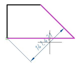
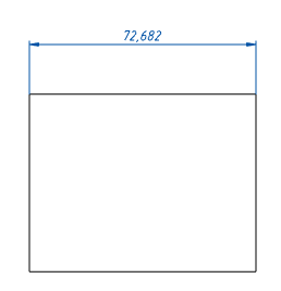
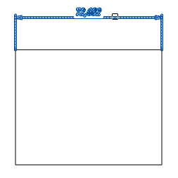
The command sets a linear horizontal dimension relationship.
1. Call command "Horizontal".
|
|
After the command is called, other dependency commands will be available in the context menu, which you can switch to if necessary. The list of dependencies is controlled by the switch "Continuous add of constraints in manual mode". |
2. Determine how to insert an equalized size: 2 points (by default when the command is called) or O-object. The method of insertion is determined by selecting the appropriate command from the context menu.
· 2 points - sets the horizontal size by two points.
· O-object - sets the horizontal size for the selected object.
3. Specify the required objects, depending on the selected insertion method.
4. Place the parametric dimension on the drawing.
5. Parametric size will be built and added to the "Parameters Manager". A variable is assigned to the parameter dimension.
|
|
If the switch is on "Continuous add of constraints in manual mode", after applying the dependency, the system will automatically switch to the insertion of the following dependency. To exit the loop, press "Esc". |
To edit the parametric size, double-click on the size. An editing dialog opens, where you can change the name of the variable and the value. The value can be a formula.
Also, the parametric size can be edited in "Parameters Manager".
Allowable objects and dependency points
· control points of objects;
· line segment;
· arc;
· segment of a polyline (rectilinear or arc).
 .
.
.
.
.
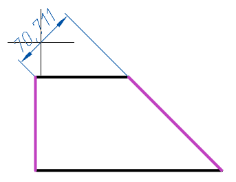
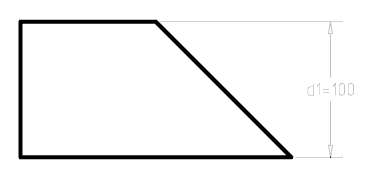
he command sets a linear vertical dimension relationship.
1. Call command "Vertical".
|
|
After the command is called, other dependency commands will be available in the context menu, which you can switch to if necessary. The list of dependencies is controlled by the switch "Continuous add of constraints in manual mode (autoadd until interrupted)". |
2. Determine how to insert an equalized size: 2 points (by default when the command is called) or O-object. The method of insertion is determined by selecting the appropriate command from the context menu.
· 2 points - sets the vertical dimension to two points.

· O-object - sets the vertical size for the selected object.
3. Specify the required objects, depending on the selected insertion method.
4. Place the parametric dimension on the drawing.
5. Parametric size will be built and added to the "Parameters Manager". A variable is assigned to the parameter dimension.
|
|
If the switch is on "Continuous add of constraints in manual mode", after applying the dependency, the system will automatically switch to the insertion of the following dependency. To exit the loop, press "Esc". |
To edit the parametric size, double-click on the size. An editing dialog opens, where you can change the name of the variable and the value. The value can be a formula.
Also, the parametric size can be edited in "Parameters Manager".
Allowable objects and dependency points
· control points of objects;
· line segment;
· arc;
· segment of a polyline (rectilinear or arc).
 .
.
.
.
.
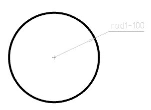
The command sets the radial dimensional dependence on an arc or circle.
1. Call command "Radial".
|
|
After the command is called, other dependency commands will be available in the context menu, which you can switch to if necessary. The list of dependencies is controlled by the switch "Continuous add of constraints in manual mode". |
2. Specify an arc or circle.
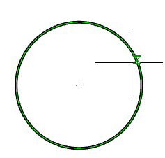
3. Arrange the parametric dimension on the drawing.
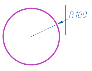
4. Parametric size will be built and added to the "Parameters Manager". A variable is assigned to the parameter dimension.
|
|
If the switch is on "Continuous add of constraints in manual mode", after applying the dependency, the system will automatically switch to the insertion of the following dependency. To exit the loop, press "Esc". |
To edit the parametric size, double-click on the size. An editing dialog opens, where you can change the name of the variable and the value. The value can be a formula.
Also, the parametric size can be edited in "Parameters Manager".
Allowable objects and dependency points
· circle;
· arc;
· arc segment of a polyline.
 .
.
.
.
.
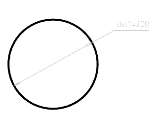
This command sets the diametrical size dependence on the arc or circle.
1. Call command "Diameter".
|
|
After the command is called, other dependency commands will be available in the context menu, which you can switch to if necessary. The list of dependencies is controlled by the switch "Continuous add of constraints in manual mode". |
2. Specify an arc or circle.
3. Arrange the parametric dimension on the drawing.
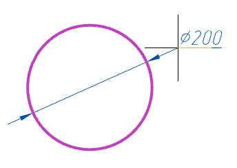
4. Parametric size will be built and added to the "Parameters Manager". A variable is assigned to the parameter dimension.
|
|
If the switch is on "Continuous add of constraints in manual mode", after applying the dependency, the system will automatically switch to the insertion of the following dependency. To exit the loop, press "Esc". |
To edit the parametric size, double-click on the size. An editing dialog opens, where you can change the name of the variable and the value. The value can be a formula.
Also, the parametric size can be edited in "Parameters Manager".
Allowable objects and dependency points
· circle;
· arc.
 .
.
.
.
.
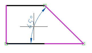
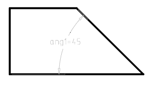
The command sets the angular dimensional relationship between the two straight lines.
1. Call command "Angular".
|
|
After the command is called, other dependency commands will be available in the context menu, which you can switch to if necessary. The list of dependencies is controlled by the switch "Continuous add of constraints in manual mode". |
2. Determine how to insert an equalized size: 2 lines (by default when the command is called) or 3-3points. The method of insertion is determined by selecting the appropriate command from the context menu.
· 2 lines - sets the angular size in two segments.
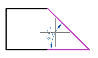
· 3-3points - sets the angular dimension. First set the vertex of the angle, then the end points.
3. Specify the required objects, depending on the selected insertion method.
4. Place the parametric dimension on the drawing.
5. Parametric size will be built and added to the "Parameters Manager". A variable is assigned to the parameter dimension.
|
|
If the switch is on "Continuous add of constraints in manual mode", after applying the dependency, the system will automatically switch to the insertion of the following dependency. To exit the loop, press "Esc". |
To edit the parametric size, double-click on the size. An editing dialog opens, where you can change the name of the variable and the value. The value can be a formula.
Also, the parametric size can be edited in "Parameters Manager".
Allowable objects and dependency points
· line segment;
· ectilinear segments of polylines;
· control points of objects;
· arc.
 .
.
.
.
.
The command converts simple dimensions to parametric.
1. Set the dimensions.
2. Call command "Dimensional constraint" and specify the dimensions for conversion.
3. The specified dimensions are converted to parametric.
 .
.
.
.
.
1. Call command "Parameters Manager". Open dialog "Parameters Manager".
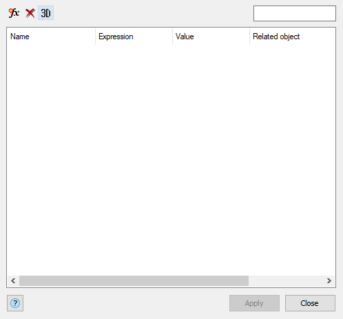
2. Edit the list of parameters.
The parameters in the list are divided into three sections:
· User Parameters - the parameters entered by the user are not tied to objects.
· Dimensional Constraints - dependencies imposed in the sketch using parametric dimensions.
· Model parameters - dependencies obtained as a result of 3D-design operations.
The list consists of four columns:
· Name - name of the parameter. You can edit.
· Expression - expression as a value or a formula that uses other parameters, operators, and functions. You can edit.
· Value - the final value when evaluating the expression. Not editable.
· Related object - the name of the object associated with the parameter. Not editable.
To manage the list, the following buttons are available:
·  Create a new user parameter - creates a new parameter that is not bound to objects.
·  Delete the selected parameter - removes any selected parameter.
|
|
Removing dimensional dependencies or model parameters, together with the parameter, the operation or dimensional dependence is deleted. |
·  Variables related to parametric 3D - switch, controls the display of 2D and 3D parameters. When the toggle is on, the user parameters for 3D and "Model parameters" are displayed, when it is off, the user parameters for 2D and "Dimensional Constraints" are displayed.
To find the required parameter, you can use the filter in the upper right corner of the form.
3. Press button "Close".
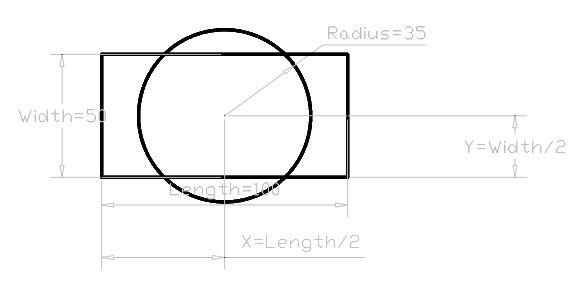
Let us create constraints for a circle and a rectangle based on 2 conditions:
Condition 1. Center of the circle is at the same point as a center of a rectangle.
Condition 2. The area of a circle is to equal to the area of a rectangle.
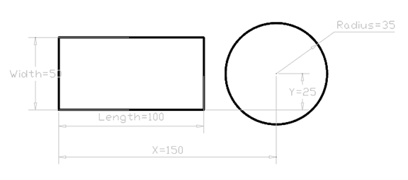
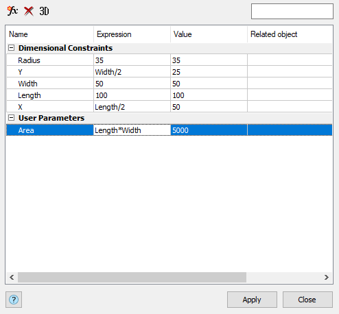
Let assign names to all dimensional constraints and set their relations.
At first we define an expression to place a center of a circle at the center of a rectangle.
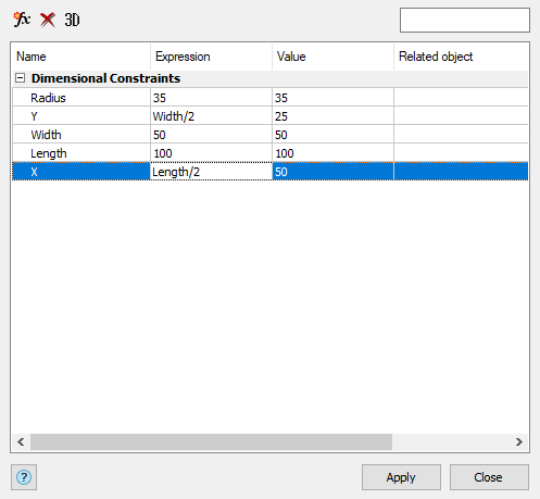
Now we define equality of areas of the circle and rectangle.
To do this, we create an Area as user parameter.
Set an expression for a radius of the circle.
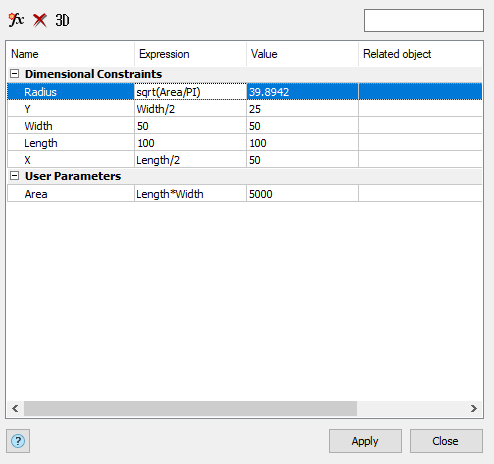
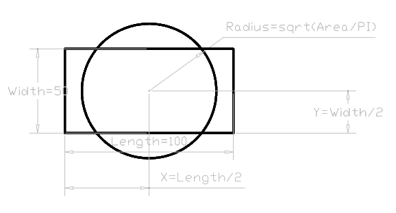
You could set equality of areas of the circle and the rectangle without definition of a user parameter by entering an expression for the Radius: sqrt((Length*Width)/PI).
The following operators can be used in expressions:
|
Operator |
Description |
|
+ |
Addition |
|
- |
Substruction or Negative |
|
% |
Modulo or Remainder operator The expression "7 % 3" would evaluate to 1, because 7 divided by 3 leaves a quotient of 2 and a remainder of 1. |
|
* |
Multiplication |
|
/ |
Division |
|
^ |
Exponentiation |
|
() |
Round brackets |
|
. |
Decimal divider |
Expressions are evaluated according to the standard mathematical rules of precedence:
1. Expressions within brackets; innermost sets first.
2. Standard operations order:
· unary negation (negative value)
· exponent
· multiplication and division
· addition and subtraction
3. Operators of equal precedence from left to right.
The following functions can be used in expressions:
|
Function |
Syntax |
|
Cosine |
cos (expression) |
|
Sine |
sin (expression) |
|
Tangent |
tan (expression) |
|
Arccosine |
acos (expression) |
|
Arcsine |
asin (expression) |
|
Arctangent |
atan (expression) |
|
Hyperbolic cosine |
cosh (expression) |
|
Hyperbolic sine |
sinh (expression) |
|
Hyperbolic tangent |
tanh (expression) |
|
Hyperbolic arccosine |
acosh (expression) |
|
Hyperbolic arcsine |
asinh (expression) |
|
Hyperbolic arctangent |
atanh (expression) |
|
Square root |
sqrt (expression) |
|
Signum-function (-1, 0, 1) |
sign (expression) |
|
Round to nearest integer |
round (expression) |
|
Truncate decimal |
trunc (expression) |
|
Round down |
floor (expression) |
|
Round up |
ceil (expression) |
|
Absolute value |
abs (expression) |
|
Largest element in array |
max (expression 1; expression 2) |
|
Smallest element in array |
min (expression 1; expression 2) |
|
Degrees to radians |
d2r (expression) |
|
Radians to degrees |
r2d (expression) |
|
Logarithm, base e |
ln (expression) |
|
Logarithm, base 10 |
log (expression) |
|
Exponent, base e |
exp (expression) |
|
Exponent, base 10 |
exp10 (expression) |
|
Power function |
pow (expression 1; expression 2) |
|
Random decimal, 0-1 |
Random |
 .
.
.
.
.
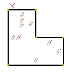
The command automatically sets constraints depending on the geometry.
1. Call command "Auto constrain".
2. Select objects to overlay dependencies. You can choose a secant frame. If the objects were selected before the command is called "Auto constrain", the process of selecting objects is skipped.
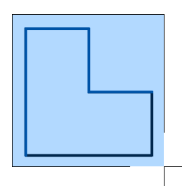
3.Press "Enter" to complete the selection of objects. The system automatically imposes the necessary dependencies.
 .
.
.
.
1. Call command "Constraint settings". Open dialog "Constraint Settings".
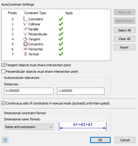
2. Configure the dependencies:
· List "AutoConstrain Settings" - allows you to set the type of dependencies and the order of their overlapping. In the "Apply" column, clicking the LMB adjusts the activity of the dependency types. Active dependency types can be used in auto-imposed dependencies.
The list is supplemented with control buttons:
· Move up - moves the selected dependency type higher in the list (increases the priority).
· Move down - moves the selected dependency type lower in the list (lowers the priority).
· Select all - makes all dependency types active.
· Clear all - makes all dependency types inactive.
· Reset - demand settings to the original settings.
· Switch "Tangent objects must share intersection point" - controls the condition that autotuning "Tangent" will occur only for objects with a common point.
· Switch "Perpendicular objects must share intersection point" - controls the condition that the "Perpendicular" autoconfiguration will occur only for objects with a common point.
· Field group "Autoconstrain tolerances":
· Distances - the maximum allowable distance between control points for automatic alignment.
· Angles -the maximum angle between objects for automatic superposition of perpendicularity and parallelism.
· Switch "Countinuous add of constraints in manual mode (autoadd until interrupted)" - controls the cyclic mode of overlay dependencies, as well as a list of dependencies in the context menu when the dependency is called.
· List Dimensional constrainr format - controls the display of the name of the dimension dependency in the drawing. When you select a format to the right of the list, its display example is displayed.
Possible options:
· Name - displays only the name of the dimension dependency.
· Value - displays the magnitude of the dimensional dependence.
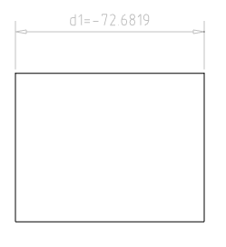
· Name and expression - displays the name of the dimension relation, as well as the parametric expression of the dependency. If no parametric expression is imposed on the dependence, then Expression=Value.
3. Press button "OK" to confirm the change of settings. The "Constraint Settings" dialog box closes.
 .
.
.
.
.
1. Call command "Show/hide constraints". If the dependencies were hidden - they will be shown, if displayed - hidden.
 .
.
.
.
.
The command removes dependencies from the selected object.
1. Call command "Delete constraints".
2. Specify the dependencies or objects for which you want to remove dependencies.
3. Press the "Enter" key. The selected dependencies, all dependencies of the selected objects, and the dependencies associated with these objects are deleted.
|
|
When you add a "Coincident" dependency, this dependency is displayed by a dot, not by an icon. At the same time, there can be several alignment relationships at one point. To remove such dependencies, in the delete dependencies mode, move the mouse cursor over the dependency point. In this case, the entire set of coincidents will unfold at this point. You can delete any of them.
|