De
De 

3D Module
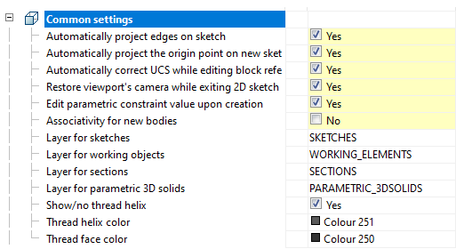
The tab is used to configure 3D settings 3D. The tab is available with a license for 3D.
· 2D views
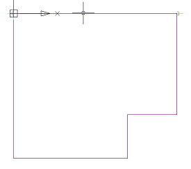
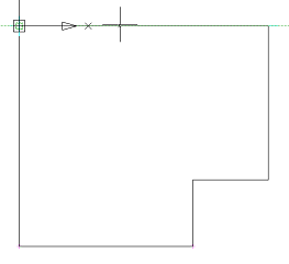
Automatically project edges on sketch
The parameter when adding a new sketch adjusts the display of the projection of the edges of a flat face taken as the working plane for the sketch.
Call command "Add planar sketch".
Specify a flat face as a work plane.
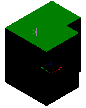
Depending on the setting, a projection will be added to the sketch.
|
Yes |
No |
|
|
|
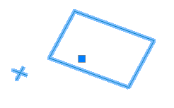
Automatically project the origin point on new sketch
Controls the projection of the origin point when creating a new sketch.
|
Yes |
No |
|
|
|
Automatically correct UCS while editing block references with 2D constraints
Automatic correction of UCS when editing a block reference with 2D constraints.
Restory viewport's camera while exiting 2D sketch editing mode
If enabled, the view camera will be in position before the sketch is edited.
Edit parametric constraint value upon creation
Controls whether the dependency editing dialog is opened immediately after installation.
Associativity for new bodies
The enabled option allows you to build fixed bodies without the possibility of defixation. The sketch must be attached to some plane.
Layer for sketches
It allows you to customize the name of the layer on which will be placed flat sketches.
Layer for working objects
It allows you to customize the name of the layer on which the objects will be located.
Layer for sections
It allows you to customize the name of the layer on which section will be located.
Layer for parametric 3D solids
Allows you to set the name of the layer on which the parametric 3D bodies will be located.
Show/no thread helix
Controls the display of the thread helix.
Thread helix color
Thread helix color.
Thread face color
Thread face color.
Mass display accuracy
Mass display accuracy for inspector properties and part and assembly unit properties.
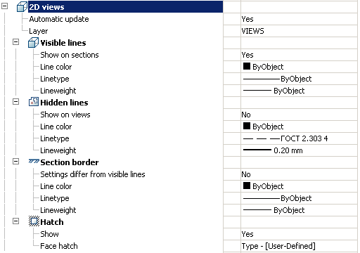
Automatic update
Sets the update mode 2D views
Layer
It defines the layer which will be located 2D views
Show on sections
Adjusts the image visible lines on sections
Line color
Specifies the color of visible lines
Linetype
Specify the type of visible lines
Lineweight
It determines the weight of visible lines
Show on sections
It adjusts the display of invisible lines on 2D views
Line color
Specifies the color of hidden lines
Linetype
Specify the type of hidden lines
Lineweight
It determines the weight of invisible lines
Settings differ from visible
It determines whether the parameters are different boundary lines of the section visible lines
If not, the next line settings are not valid.
Line color
Specifies the color of the boundary line section
Linetype
Specifies the type of the boundary line section
Lineweight
It determines the weight of the boundary line section
Show
It controls the display of hatching
Face hatch
Settings such as shading
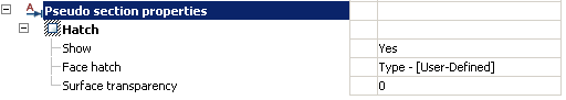
Show
It controls the display of hatching.
Face hatch
Settings such as shading.
Surface transparency
Settings such as shading. Default 0 - full transparency.
 Main menu: 3D -
  3D History...
Ribbon: 3D Tools - Modeling - 3D History.
Functional panel: 3D History.
 Command line: SHOWTAB3DHISTORYNET.
Command line: TABS - select "3D History".
When working in the 3D-design environment, a functional panel containing the model building tree is displayed on the screen.
Building tree - sequence of objects (actions) that make up the model.
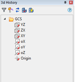
The build tree contains a set of tools:
 Filter Items - massively hides all working objects: planes, axes, points.
 Update tree - updates the tree.
 Expand parts - expands all branches in the tree.
 Expand parts with errors - expands branches of parts that have errors.
 Collapse parts - collapses all expanded branches in the tree.
 Update model with regen(3drebuild) - rebuild model.
 Update model(mchist3dupdate) - update model.
 Assembly properties - opens the "Properties of an assembly unit" dialog, where the data of the selected object for the specification is specified.
 - root folder "GCS" (General Coordinate System).
The following objects are bound to it:
·  - planes YZ, ZX, XY. By default, they are hidden and have a gray icon
  .
.
The following shortcut menu commands are available:
· Hide - hides the mapping of the plane in model space.
· Show - shows the mapping of the plane in model space.
· ShowInDocument - focuses the plane in the center of the model space. The command is available when the plane is displayed.
· Create 2d-sketch - call command "Add planar sketch". Sketch drawing plane is not necessary.
·  - axis oX, oY, oZ. By default, they are hidden and have a gray icon
  .
.
The following shortcut menu commands are available:
· Hide - the command hides the display of the axis in model space.
· Show - the command displays the axis in model space.
· ShowInDocument - the team focuses the axis in the center of the model space. The command is available when the axis is displayed.
·  - origin. Default is hidden and has a gray icon
  .
.
The following shortcut menu commands are available:
· Hide - the command hides the display of the origin in the model space.
· Show - the command shows the display of the origin in the model space.
· ShowInDocument - the team focuses the origin in the center of the model space. The command is available when the origin is displayed.
- root folder "Sections".
The following objects are bound to it:
·  - Section. Has child objects
  View, taken from section.
 - Planar sketch. When applied to it, 3D Operations is bound to an operation (becomes its child element) and the icon becomes inactive. An exception - assembly sketch.
 - Part. It is a 3D object. Sheet bodies have their own icon
  .
.
The following objects can be attached to the part:
·  "Work plane". Can be located in the root of the tree and enter the structure of objects "Part".
·  "Work axis". Can be located in the root of the tree and enter the structure of objects "Part".
·  "Work point". Can be located in the root of the tree and enter the structure of objects "Part".
·  "McExtrudeFeature". 3D operation.
·  "McRevolveFeature". 3D operation.
·  "McSweepFeature". 3D operation.
·  "McLoftFeature". 3D operation.
·  "Union". Contains the union parts.
·  "Intersect". Contains the intersect parts.
·  "Subtract". Contains the substract parts.
·  "McRectangularPatternFeature".
· 


 - 3D constraints.
·  Nonparametric solid.
·  End of builds. The object indicates the end of the body construction.
The following shortcut menu commands are available for the object "Part":
· Rename (F2) - allows you to rename the part.
· Delete (Del) - removes the part and child objects from the tree and model space.
· Hide - hides the part and child objects from the model space.
· Show - shows the part and child objects in the model space.
· Fix - fixes the part in space. You can not move (3D Move), rotate (3D Rotate) or align (3D Align). The part acquires an icon with an anchor  .
.
· Unfix - de-fixes the part. You can move (3D Move), rotate (3D Rotate) or align (3D Align).
· ShowInDocument - focuses and highlights the part in the center of the model space.
· Rebuild - rebuilds an object in model space.
· Create detail - creates a detail from the part, internal objects are hidden. The detail is a 3d block.
Detail - the object is a 3D block.
The following shortcut menu commands are available for the object "Detail":
· Open in editor - opens the 3D block editor.
· Edit in place - opens the 3D reference editor.
· Rename (F2) - allows you to rename the detail.
· Delete (Del) - removes the detail and child objects from the tree and model space.
· Hide - hides the detail and child objects from the model space.
· Show - shows the detail and child objects in the model space.
· Fix - fixes the detail in space. You can not move (3D Move), rotate (3D Rotate) or align (3D Align). The detail acquires an icon with an anchor .
· Unfix - de-fixes the detail. You can move (3D Move), rotate (3D Rotate) or align (3D Align).
· ShowInDocument - focuses and highlights the detail in the center of the model space.
· Rebuild - rebuilds an object in model space.
· Disband - breaks a detail (assembly) into its component parts.
· Create assembly - the command is active when two or more parts (details, assemblies) are selected and creates an assembly unit  . The assembly is a 3d block.
· Properties - command opens the "Properties" dialog.
Assembly - an object is a 3d block that includes several units of parts, bodies, assemblies. Context menu commands are similar to the object "Detail":
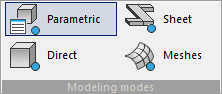
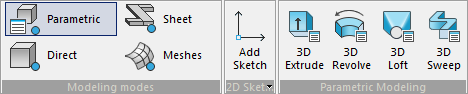
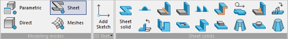
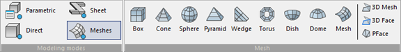
Various types of modeling are used in the design process: Parametric, Direct, Sheet, Meshes.
Placing all of the commands for these types of modeling on the same tab at the same time creates confusion.
For the convenience of designing, the "Modeling modes" ribbon block has been added, which includes the following commands:
Ribbon: 3D Tools - Modeling modes -  Parametric.
Command line: 3DDRAFTINGMODE0.
Opens ribbon blocks "Parametric Modeling", "2D Sketch".
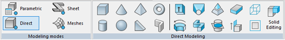
Ribbon: 3D Tools - Modeling modes -  Direct.
Command line: 3DDRAFTINGMODE1.
Opens ribbon block "Direct Modeling".
Ribbon: 3D Tools - Modeling modes -  Sheet.
Command line: 3DDRAFTINGMODE2.
Opens ribbon blocks "Sheet solids", "2D Sketch".
Ribbon: 3D Tools - Modeling modes -  Meshes.
Command line: 3DDRAFTINGMODE3.
Opens ribbon block "Mesh".
Main menu: 3D - 2D Sketch -  Add planar sketch.
Ribbon: 3D Tools - 2D Sketch - Add sketch.
Toolbar: 3D - Add planar sketch.
Command line: PSADD.
There are 2 ways to create a sketch, with a reference to the plane and without binding.
With a sketch without binding, a 3D operation is created in the new unfixed body.
From the sketch with reference to the plane of the body, a 3D operation is created with a binding to the body.
From a sketch bound to a plane that does not belong to the body, a 3D operation is created in the new fixed body without the possibility of de-fixing.
|
Important! |
When creating a sketch that will serve as a cross-section for 3D design operations, it is important to remember that the sketch must be a closed loop. |
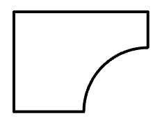
Creating a sketch without a reference to the plane
Sketching without reference to a plane is done in the XY plane.
1. Draw a sketch.
2. Select all sketch entities.
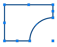
3. Call command "Add planar sketch". The system automatically sets the desired view orientation. All the available objects in the sketch will be transferred from the selected objects.
5. A sketch without reference to a plane will be created and added to "3D History".
Creating a sketch with a reference to the plane
1. Call command "Add planar sketch".
2. Select the sketch creation plane. This can be a plane GCS, any working plane, as well as a flat surface of the body. The system automatically sets the desired orientation of the view - normal to the selected plane.
3. Draw a sketch.
For convenience, in sketch editing mode, the ribbon contains all the necessary commands to draw a sketch, edit its geometry, project some face, or complete sketch editing.

5. A sketch with a reference to the plane will be created and added to "3D History".
Does not have individual properties.
 Moving grip - is used to move the sketch in model space.
"Planar sketch". When creating Planar sketch is located in the root of the tree. When applied to it, 3D Operations is bound to an operation (becomes its child element) and the icon becomes inactive. An exception - Assembly sketch.
he following shortcut menu commands are available:
· Edit - Calls to edit the sketch. To the right of the icon appears the editing symbol  .
.
· End edit - completes the previously started editing.
· Rename (F2) - allows you to rename a sketch.
· Delete (Del) - removes a sketch from the tree and model space.
· Hide - hides a sketch from the model space. The icon becomes inactive.
· Show - shows a sketch in model space. The icon becomes active.
· Suppress - removes the thumbnail from the model space. The icon becomes inactive. Suppressed elements are removed only from the model space, while they remain in the build tree. After suppressing the element, the model will be rebuilt without taking into account the excluded elements and their derivatives.
· Unsuppress - restores a sketch in model space.
· ShowInDocument - focuses and highlights the sketch in the center of the model space.
· Rebuild - rebuilds the object in model space.
Main menu: 3D - 2D Sketch -  Add assembly sketch.
Toolbar: 3D - Add assembly sketch.
Command line: PSADDASM.
The command is similar "Add planar sketch".
Differences of the assembly sketch
· the assembly sketch is not included in any body, including in the model tree;
· the body constructed from the assembly sketch is automatically fixed in the last position without the possibility of a defect;
· the body built from the assembly sketch can only be moved together with the assembly sketch. You can only move the sketch.
Main menu: 3D - 2D Sketch -  Include object to sketch.
Ribbon: 3D Tools - 2D Sketch - Include Object.
Toolbar: 3D - Include object to sketch.
Command line: PSINCL.
The command is used to add objects not built in sketch mode to the sketch. The command is available in the mode of creating (editing) the sketch.
1. In sketch editing mode, call the command "Include object to sketch".
2. Specify the objects that you want to add to the sketch. The object is added to the sketch.
3. To exit the add mode, press "Esc".
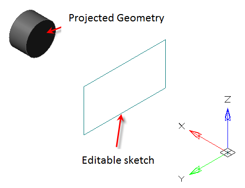
Main menu: 3D - 2D Sketch -  Add projection to sketch.
Ribbon: 3D Tools - 2D Sketch - Add Projection.
Toolbar: 3D - Add projection to sketch.
Command line: PSPROJ.
The team projects geometry that is not built in sketch mode. It is also possible to project the geometry from the bodies. The command is available in the mode of creating (editing) the sketch.
1. In sketch editing mode, call the command "Add projection to sketch".
2. Sequentially indicate the edges of the object that you want to project. The projection is performed automatically immediately after the indication.
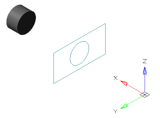
3. To exit the loop, press "Esc".
|
Important! |
When you remove the projected geometry, the projection is removed along with the geometry. |
Projected geometry in a sketch can be redefined to another of that type. In this case, all associative bindings are preserved.
To override you need:
1. Call the sketch for editing;
2. Select the projected geometry;
3. Call the RMB context menu and select the "Redefine" command;
4. Specify another edge of the object, it must have the same type (line, circle...);
5. The geometry will be redefined. Associative links will be preserved.
Main menu: 3D - 2D Sketch -  Redefine plane for sketch.
Ribbon: 3D Tools - 2D Sketch - Redefine Plane.
Toolbar: 3D - Redefine plane for sketch.
Command line: PSREDEFINE.
The command changes the plane of the selected sketch to another flat surface or work plane.
1. Call command "Redefine plane for sketch".
2. Select in the model space or in the "3D History" sketch to move.
3. Select a new plane for the sketch in model space, in "3D History" or GCS plane from the context menu.
4. The sketch will be automatically moved to another plane.
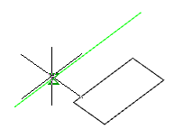
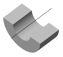
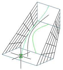
Main menu: 3D - 2D Sketch -  Set Sketch Coordinate System.
Ribbon: 3D Tools - 2D Sketch - Set Sketch Coordinate System.
Toolbar: 3D - Set Sketch Coordinate System.
Command line: PSDEFINECS.
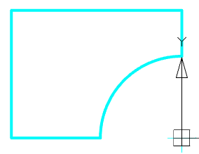
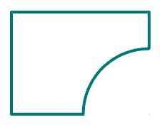
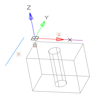
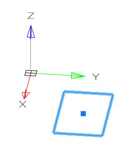
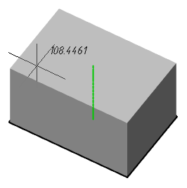
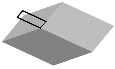
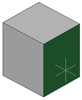
When you sketch on a planar face or work plane, the system automatically creates the sketch coordinate system. The "Set Sketch Coordinate System" command is required to edit the coordinate system of the selected sketch.
1. A sketch must first be created on a work plane or planar face.
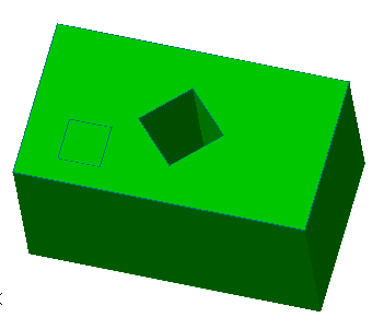
2. Call command "Set Sketch Coordinate System" and specify a flat sketch if necessary.
3. The sketch coordinate system is displayed.
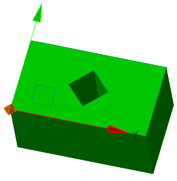
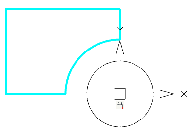
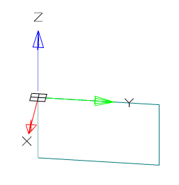
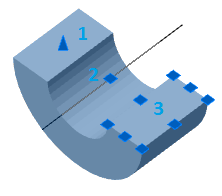
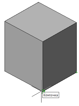
4. Select the item to change. The X, Y axis, or the origin point can be used as the element to change.
|
Point |
Axis |
|
|
|
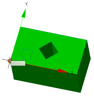
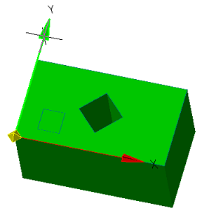
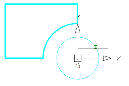
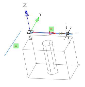
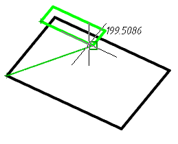
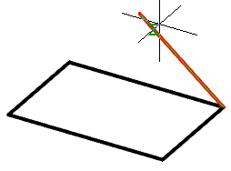
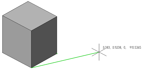
5. Pick a new position for the element. To change the origin, you need to specify a new point; to change the direction of the axis, you need to specify any straight edge. The position of the sketch relative to its coordinate system does not change.
|
Point |
Axis |
|
|
|
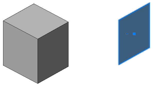
6. The sketch coordinate system will be changed.
Main menu: 3D - 2D Sketch -  Edit planar sketch.
Ribbon: 3D Tools - 2D Sketch - Edit sketch.
Toolbar: 3D - Edit planar sketch.
Command line: PSEDIT.
Context menu: Command "Edit" on select sketch in "3D History".
The command switches to edit mode a flat sketch.
1. Specify in the model space or in the "3D History" sketch.
2. Call command "Edit planar sketch".
3. The sketch will go into edit mode.
Main menu: 3D - 2D Sketch -  End editing.
Ribbon: 3D Tools - 2D Sketch - End editing.
Toolbar: 3D - End editing.
Command line: PSENDEDIT.
The command finishes creating or editing a sketch.
Main menu: 3D - 3D Features -  3D Extrude.
Ribbon: 3D Tools - Modeling - 3D Extrude.
Toolbar: 3D - 3D Extrude.
Command line: 3DEXTRUDE.
Tool for pulling a section along a straight path.
1. Create a Planar sketch (if it is not).
2. Call command "3D Extrude". Open dialog "3D Extrude".
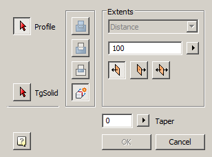
3. Specify the required options in the dialog box "3D Extrude":
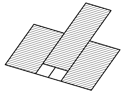
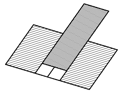
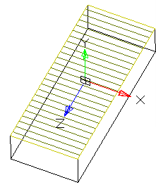
· Select the section sketch. Possible sketches are highlighted by horizontal hatching. The selected section is highlighted by vertical shading. The sketch must be a closed loop.
|
Note: |
If you have already selected a section from one sketch, and you want to select another section from another sketch, you must first deselect the section you have already selected. |
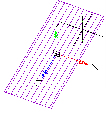
Simultaneously with the selection of the section, a contour of the extruded section appears - a preview of the result of the operation.
· Set the extrusion distance.
· Choose a direction: Positive, Negative, Both directions.
· Specify, if necessary, the slope of the extrusion.
4. Press button "OK". The operation will be carried out. If the "OK" button is not active, then the sketch was not selected or the parameters were incorrectly set. In the "3D History" will be created object "McExtrudeFeature", containing a sketch, linked to an existing or a new body.
Button  "Profile" - allows you to select in the model space or in the "3D History" sketch.
Button "TgSolid" - allows you to specify the parent body for the sketch.
Switch "New body is associative" - controls the settings parameter "Associativity when creating new bodies". The enabled
option allows you to build fixed bodies without the possibility of defixation.
A group of operation action selectors:
·  "Join" - creates a new extrusion object in the previously created body. The sketch must belong to the body.
·  "Cut" - creates a cutout with the outline of the selected sketch (for example, holes). When cutting, the dimension selection field becomes active, allowing you to select the cut length to a distance or through. The sketch must belong to the body.
·  "Intersect" - creates an object to intersect the contours of the new sketch and the previously created body. The sketch must belong to the body.
·  "New body" - creates a new extrusion object. A new body appears in the tree of constructions. When a switch is selected, the previously selected sketch belonging to the body is detached from the body.
Extends:
·  "The field for selecting the type of dimension". Distance - extrusion, cutting or intersection is specified by the distance. All - cutting is carried out through the whole body, the distance input field is unavailable.
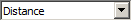
· Field 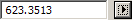 "Distance" - allows you to specify the distance. To the right of the field, there is a button to indicate the distance from the drawing.
·  "Group of direction selection switches" - controls the direction of extrusion relative to the sketch plane.
 Positive direction - directs the extrusion towards the positive direction of the axis perpendicular to the plane of the sketch.
 Negative direction -directs the extrusion towards the negative direction of the axis perpendicular to the plane of the sketch.
 Both direction - directs extrusion in both directions relative to the sketch plane by the same distance.
Field "Angle of slope" - allows you to specify the angle of inclination. The operation creates a body tapering to a point. To the right of the field there is a button for specifying the angle from the drawing.
|
Note: |
When choosing the faces of an existing body for building 3D-operations, it is recommended to disable the Center binding in order to avoid incorrect work. |
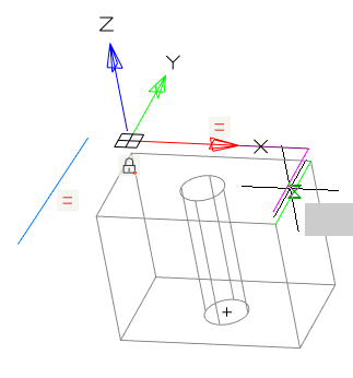
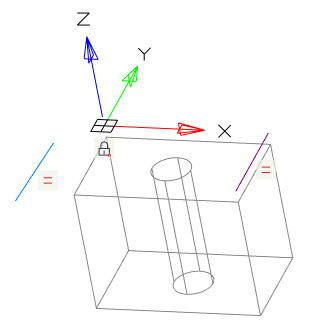
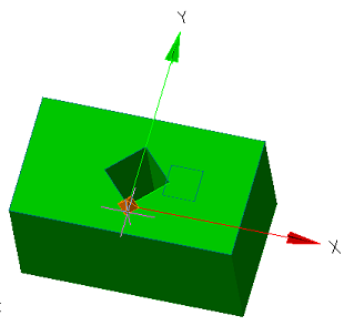
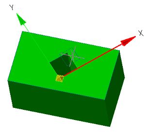
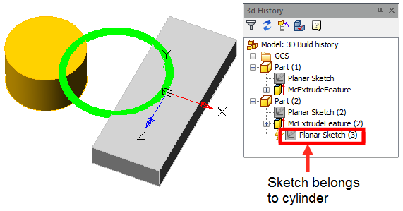
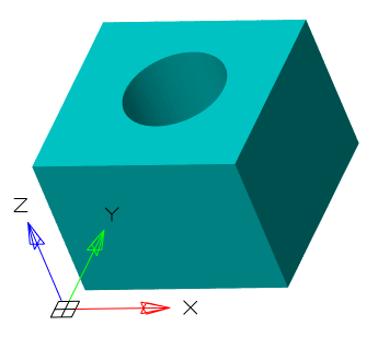
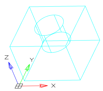
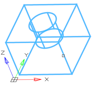
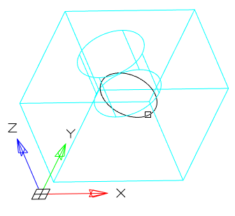
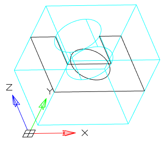
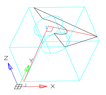
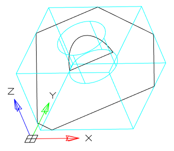
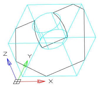
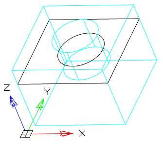
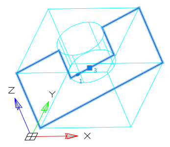
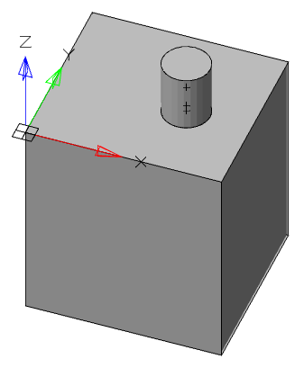
There are two bodies: a cylinder and a parallelepiped. On the upper plane of the cylinder a sketch is created, which is a circle whose center is located between these bodies.
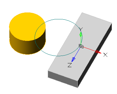
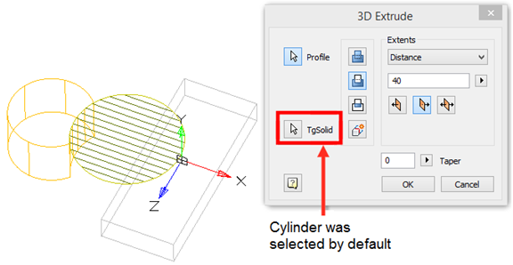
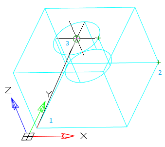
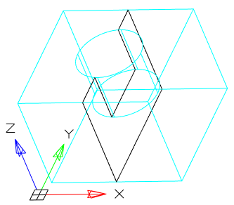
Call the "3D Extrude" dialog and select this circle as the sketch. As an action, select "Cut". By default, the sketch belongs to the body on whose plane it was built, in this case the cylinder. Correspondingly, the cutting will be performed for the cylinder.
By default, the body of the cylinder is selected.
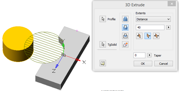
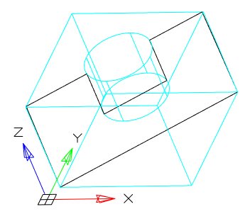
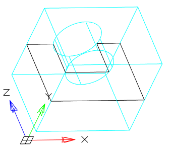
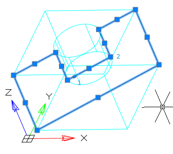
Assign a new body to the parallelepiped, for which we click on the button "TgSolid" and the LMC we select a parallelepiped.
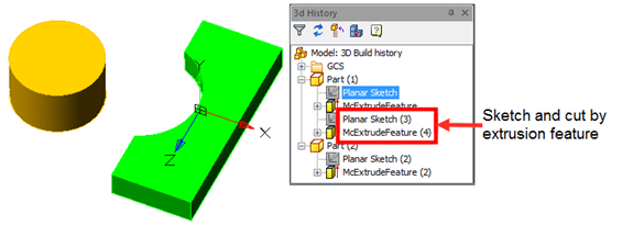
Result: the sketch belongs to the body of Parallelepiped, is part of its tree, and makes a cutout in its body.
"McExtrudeFeature". It is part of the body.
The following shortcut menu commands are available:
· Edit - calls for editing a 3D operation. To the right of the icon appears the editing symbol .
· End edit - completes the previously started editing.
· Rename (F2) - allows you to rename a 3D operation.
· Delete (Del) - removes the 3D operation and child objects from the tree and model space.
· Suppress - removes the 3D operation and child objects from the model space.
· Unsuppress - restores a 3D operation in model space.
· ShowInDocument - focuses and highlights the 3D operation in the center of the model space.
· Rebuild - rebuilds the object in model space.
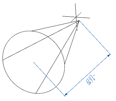
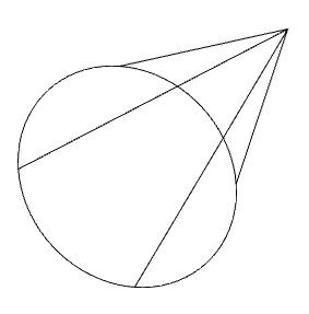
Main menu: 3D - 3D Features -  3D Revolve.
Ribbon: 3D Tools - Modeling - 3D Revolve.
Toolbar: 3D - 3D Revolve.
Command line: 3DREVOLVE.
Tool for drawing a section along a path in the form of a circle or a circular segment.
1. Create a Planar sketch (if it is not).
2. Create a working axis, if necessary, around which the rotation will take place. The face of the body can also serve as an axis.
3. Call command "3D Revolve". Open dialog "3D Revolve".
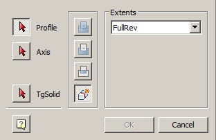
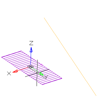
4. Specify the required options in the dialog box "3D Revolve":
· Select the section sketch. Possible sketches are highlighted by horizontal hatching. The selected section is highlighted by vertical shading. The sketch must be a closed loop.
|
Note: |
If you have already selected a section from one sketch, and you want to select another section from another sketch, you must first deselect the section you have already selected. |
· Select the axis of rotation. You can select the line in the drawing, including the line that is part of the sketch, as well as the edge of the body. A preview of the results of the operation appears.
· Set the rotation angle and direction if necessary.
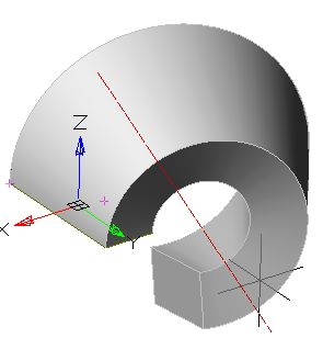
5. Press button "OK". The operation will be carried out. If the "OK" button is not active, then the sketch, axis, or incorrect parameters were not selected. In the "3D History" will be created object "McRevolveFeature", a sketch containing a sketch, linked to an existing or a new body.
|
Note: |
When choosing the faces of an existing body for building 3D-operations, it is recommended to disable the Center binding in order to avoid incorrect work. |
Button "Profile" - allows you to select in the model space or in the "3D History" sketch.
Button "Axis" - allows you to select the axis of rotation in the model space or in the "3D History".
Button "TgSolid" - allows you to specify the parent body for the sketch (for more information about the function, see Extrude).
Switch "New body is associative" - controls the settings parameter "Associativity when creating new bodies". The enabled option allows you to build fixed bodies without the possibility of defixation.
A group of operation action selectors:
· "Join" - creates a new object by rotating in the previously created body. The sketch must belong to the body.
· "Cut" - creates a cutout by rotating the selected sketch (for example, holes). The sketch must belong to the body.
· "Intersect" - creates an object to intersect the contours of the new sketch and the previously created body. The sketch must belong to the body.
· "New body" - creates a new rotation object. A new body appears in the tree of constructions. When a switch is selected, the previously selected sketch belonging to the body is detached from the body.
Extents:
·  "The field for selecting the type of dimension". RevAngle - rotation is given by the angle. FullRev - rotation is performed on a full circle.
· Field 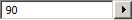 "Angle" - allows you to specify the rotation angle. To the right of the field there is a button for specifying the angle from the drawing.
·  "Group of direction selection switches" - controls the direction of extrusion relative to the sketch plane.
 Positive direction - directs the rotation toward the positive direction of the axis perpendicular to the plane of the sketch.
 Negative direction - directs the rotation toward the negative direction of the axis perpendicular to the plane of the sketch.
 Both direction - directs the rotation in both directions relative to the sketch plane by the same distance.
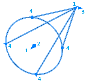
"McRevolveFeature". It is part of the body.
The following shortcut menu commands are available:
· Edit - calls for editing a 3D operation. To the right of the icon appears the editing symbol .
· End edit - completes the previously started editing.
· Rename (F2) - allows you to rename a 3D operation.
· Delete (Del) - removes the 3D operation and child objects from the tree and model space.
· Suppress - removes the 3D operation and child objects from the model space.
· Unsuppress - restores a 3D operation in model space.
· ShowInDocument - focuses and highlights the 3D operation in the center of the model space.
· Rebuild - rebuilds the object in model space.
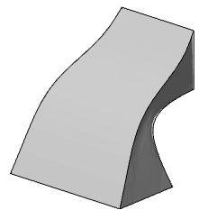
Main menu: 3D - 3D Features -  3D Sweep.
Ribbon: 3D Tools - Modeling - 3D Sweep.
Toolbar: 3D - 3D Sweep.
Command line: 3DSWEEP.
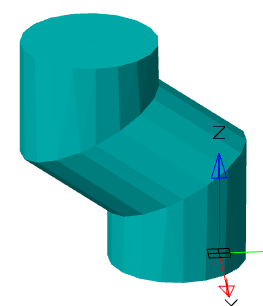
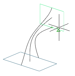
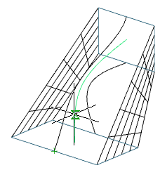
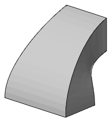
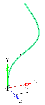
Tool for drawing a section along a previously trajectory.
1. Create a Planar sketch (if not).
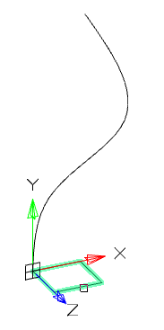
2. Create a path along which the section will be drawn. The trajectory must be drawn in another sketch mode in the orthogonal plane to the section plane.
3. Call command "3D Sweep". Open dialog "3D Sweep".
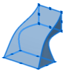
4. Specify the required options in the dialog box "3D Sweep":
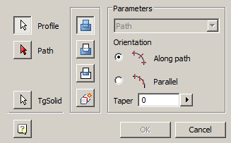
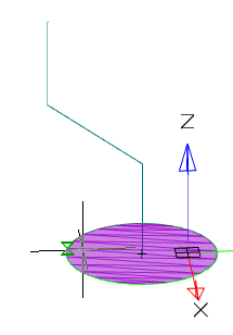
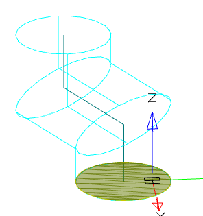
· Select the section sketch. Possible sketches are highlighted with purple fill. The sketch must be a closed loop.
|
Note: |
If you have already selected a section from one sketch, and you want to select another section from another sketch, you must first deselect the section you have already selected. |
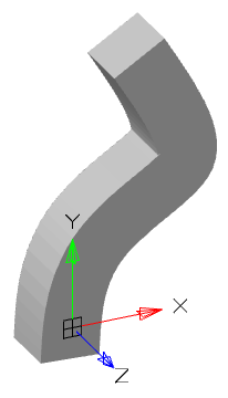
The selected section is highlighted with a green fill.
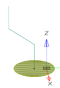
· Select a path. If the path is a polyline or a combination of individual lines, you must select a path in sequence. To exclude from the sequence an incorrectly selected path segment, you must click on it LMC + Shift.
· Select an orientation.
|
Along path |
Parallel |
|
|
|
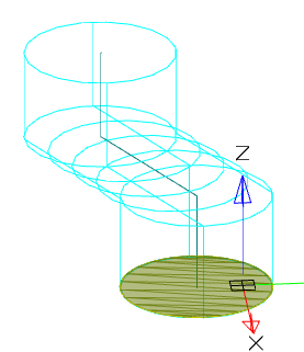
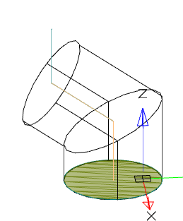
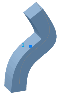
· If necessary, specify the broadening (if the orientation is selected along the path).
5. Press button "OK". The operation will be carried out. If the "OK" button is not active, then the sketch, the trajectory was not selected, or the parameters were incorrectly set. In the "3D History" will be create object "McSweepFeature", containing a sketch and trajectory, with reference to an existing or a new body.
|
Note: |
When choosing the faces of an existing body for building 3D-operations, it is recommended to disable the Center binding in order to avoid incorrect work. |
Button "Profile" - allows you to select in the model space or in the "3D History" sketch.
Button "Path" - allows you to select a trajectory in the model space or in the "3D History".
Button "TgSolid" - allows you to specify the parent body for the sketch (For more information about the function, see Extrude).
Switch "New body is associative" - controls the settings parameter "Associativity when creating new bodies". The enabled option allows you to build fixed bodies without the possibility of defixation.
A group of operation action selectors:
· "Join" - creates a new draw object in the previously created body. The sketch must belong to the body.
· "Cut" - creates a cutout by drawing out the selected sketch (for example, holes). The sketch must belong to the body.
· "Intersect" - creates an object to intersect the contours of the new sketch and the previously created body. The sketch must belong to the body.
· "New body" - creates a new draw object. A new body appears in the tree of constructions. When a switch is selected, the previously selected sketch belonging to the body is detached from the body.
Parameters:
·  "The field for selecting the type of dimension". Path - The pull length is given by the path. The field is not active.
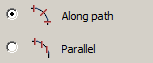
· Radiogroup "Orientation" - controls the orientation of the sketch sections: Along path - sections are drawn perpendicular to the path line; Parallel - sections are built parallel to the sketch.
· Field  "Taper" - allows you to specify the angle of broadening. To the right of the field there is a button for specifying the angle from the drawing. The field is active when the track is oriented.
"McSweepFeature". It is part of the body. Contains sketch and  "Path".
The following shortcut menu commands are available for the object "McSweepFeature":
· Edit - calls for editing a 3D operation. To the right of the icon appears the editing symbol .
· End edit - completes the previously started editing.
· Rename (F2) - allows you to rename a 3D operation.
· Delete (Del) - removes the 3D operation and child objects from the tree and model space.
· Suppress - removes the 3D operation and child objects from the model space.
· Unsuppress - restores a 3D operation in model space.
· ShowInDocument - focuses and highlights the 3D operation in the center of the model space.
· Rebuild - rebuilds an object in model space.
The following shortcut menu commands are available for the object "Path":
· Edit - causes editing of the trajectory.
· End edit - completes the previously started editing.
· Hide - hides the trajectory from the model space.
· Show - shows the trajectory in the model space.
· ShowInDocument - focuses and highlights the trajectory in the center of the model space.
· Rebuild - rebuilds an object in model space.
Main menu: 3D - 3D Features -  3D Loft.
Ribbon: 3D Tools - Modeling - 3D Loft.
Toolbar: 3D - 3D Loft.
Command line: 3DLOFT.
Tool for drawing bodies with different sections.
1. Create Planar sketches with sections.
2. Call command "3D Loft". Open dialog "3D Loft".
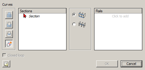
3. Specify the required options in the dialog box "3D Loft":
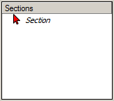
· Select the first section. The sketch of a section must be a closed contour. The first section in the list can not be deleted. By clicking the "Delete" button, the geometry set for this section is cleared. After that, the geometry can be selected again. In the dialog, changing the color of the arrow means that the contour of the section is selected and you can proceed to select the next forming section.
· Add the following sections. To add a section, click the "Add" button. When adding sections, the preliminary result of the operation will be shown. The number of forming sections is not limited.
|
Note: |
You can not add a new section without completing the geometry selection for the previous section. |
|
Note: |
If you have already selected a section from one sketch, and you want to select another section from another sketch, you must first deselect the section you have already selected. |
· Select the type of rails: Rails or Center line. For more information on rails, see below.
· If necessary, specify Rails or Center line. For more information on guides, see below.
4. Press button "OK". The operation will be performed.
Switch "Associative" - controls the settings parameter "Associativity when creating new bodies". The enabled option allows you to build fixed bodies without the possibility of defixation.
A group of operation action selectors:
· "Join" - creates a new object in the previously created body. The sketch must belong to the body.
· "Cut" - creates a cutout. The sketch must belong to the body.
· "Intersect" - creates an object to intersect the contours of the new sketch and the previously created body. The sketch must belong to the body.
· "New body" - creates a new object. A new body appears in the tree of constructions. When a switch is selected, the previously selected sketch belonging to the body is detached from the body.
Ribbon Selection Panel:
·  Rails
Rails
·  Center line
List of sections. Contains a list of selected sections
List of rails. Contains a list of selected curve rails.
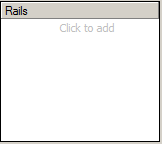
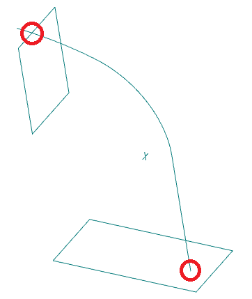
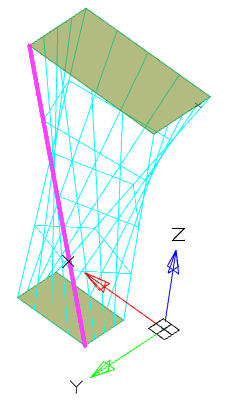
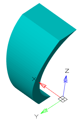
Rails determine the form of stretching across sections between sections.
Rails can be 2D or 3D curves or edges of an existing body. The number of rails is unlimited. Rails affect the whole form of stretching across sections, not just vertices.
Rails must pass strictly through each contour of drawing by sections. In this case, the start of the rail must be strictly on the contour of the first section, the end of the rail strictly on the contour of the last section.
Rail must not be interrupted.
It is possible to construct closed rails - in this case a closed body will be constructed.
The following guide curves are not allowed:
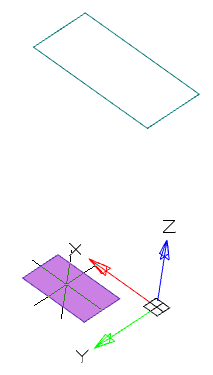
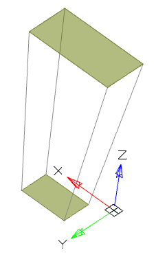
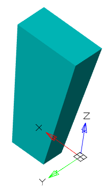
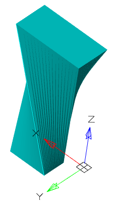
Example of using rails:
|
Without the use of rails |
Using rails |
|
|
|
|
|
|
|
Note: |
Rail curves do not work when the "Close" option is selected. |
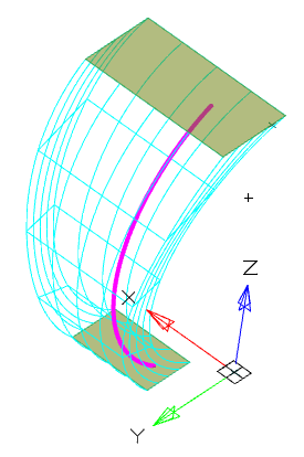
The centerline is the type of the railing curve. The center line must pass through each section. The center line can be only one.
|
Without using a center line |
Using a center line |
|
|
|
|
|
|
"McLoftFeature". It is part of the body. Contains a list  "Section".
The following shortcut menu commands are available for the object "McLoftFeature":
· Edit - calls for editing a 3D operation. To the right of the icon appears the editing symbol .
· End edit - completes the previously started editing.
· Rename (F2) - allows you to rename a 3D operation.
· Delete (Del) - removes the 3D operation and child objects from the tree and model space.
· Suppress - removes the 3D operation and child objects from the model space.
· Unsuppress - restores a 3D operation in model space.
· ShowInDocument - focuses and highlights the 3D operation in the center of the model space.
· Rebuild - rebuilds the object in model space.
3D operation "McLoftFeature" there are child objects "Section".
The following shortcut menu commands are available for the object "Section":
· Delete (Del) - removes the section from the tree and model space.
Main menu: 3D -  Rebuild 3D model.
Ribbon: 3D Tools - Modeling - Rebuild Model.
Functional panel:3D History -  Rebuild 3D model.
Command line: 3DREBUILD.
Tool for updating model parameters.
The section "3D Solids" describes the creation of dwg-compatible 3D solids. The resulting objects can be edited using standard AutoCAD tools.
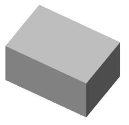
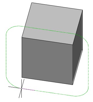
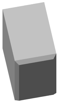
Main menu: 3D - Solid -  Box.
Box.
Ribbon: 3D Tools - 3D Solids - Box.
Toolbar: 3D Solid - Box.
Command line: 3DBOX.
The command create 3D solid - Box.
1. Call command "Box".
2. Choose a point of reference (via context menu or command line): "Corner" (default) or "Center".
· Corner - the sides of the box are counted from the specified point.
· Center - the sides are counted evenly from the center.
3. Specify the starting point in the selected way.
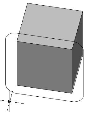
4. Choose a base construction method: "Corner" (default), "Cube" or "Length".
· Corner - a rectangle is constructed when specifying the second point.
· Cube - the length, width and height will be the same and after specifying the point the box will be built.
· Length - alternately indicate the length and width of the base.
5. Build the base in the chosen way.
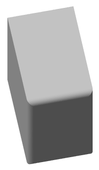
6. Select the method of setting the height: "Height" (default) or "DistanceBy2Point".
· Height - the height of the box is set in the drawing or in the command line.
· DistanceBy2Point - the height of the box is specified by specifying two points in the drawing.
7. Specify the height of the selected method.
8. The box will be built.
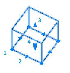
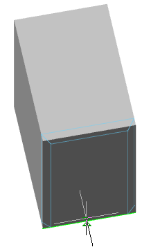
1. Grips change the width and length of the base.
2. Grips change the width or length of the base.
3. Grips change the height of the box.
4. Grip moving object.
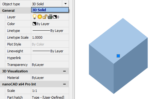
 "3D solid". It is part of the body.
The following context menu commands are available:
· Rename (F2) - allows you to rename an object.
· Delete (Del) - removes an object and child objects from the tree and model space.
· ShowInDocument - focuses and highlights the object in the center of the model space.
· Rebuild - rearranges the object in the model space.
Main menu: 3D - Solid -  Cylinder.
Ribbon: 3D Tools - 3D Solids - Cylinder.
Toolbar: 3D Solid - Cylinder.
Command line: 3DCYLINDER.
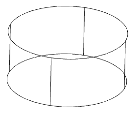
The command create 3D solid - Cylinder.
1. Call command "Cylinder".
2. Choose a base construction method:
· Base center (default) - the circle is built in the center and radius.
· 3Point - the circle is built at three points.
· RoundBaseBy2Point - build a circle at two points.
· Incircle round base - a circle is constructed along two tangents.
· Elliptical - an ellipse is built along the center, half-line and radius.
3. Specify the necessary parameters depending on the chosen method of building the foundation. The foundation will be built.
4. Choose a way to specify the height of the cylinder:
· Height - indicates the height in the drawing or on the command line.
· DistanceBy2Point - height is calculated by the specified two points in the drawing.
· Axis endpoint - height and direction are calculated at the specified point in the drawing, the first reference point is the center of the base.
5. Specify the required parameters depending on the selected method of specifying the height.
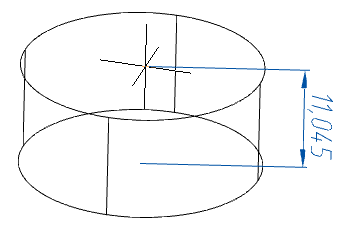
6. The cylinder will be built.
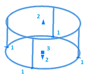
1. Grips change the radius of the base.
2. Grips change the height of the cylinder.
3. Grip move.
"3D solid". It is part of the body.
The following context menu commands are available:
· Rename (F2) - allows you to rename an object.
· Delete (Del) - removes an object and child objects from the tree and model space.
· ShowInDocument - focuses and highlights the object in the center of the model space.
· Rebuild - rearranges the object in the model space.
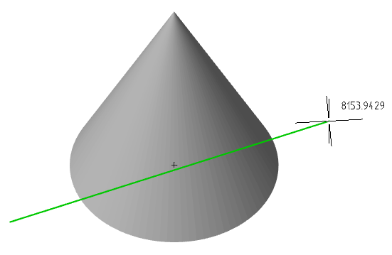
Main menu: 3D - Solid -  Cone.
Cone.
Ribbon: 3D Tools - 3D Solids - Cone.
Toolbar: 3D Solid - Cone.
Command line: 3DCONE.
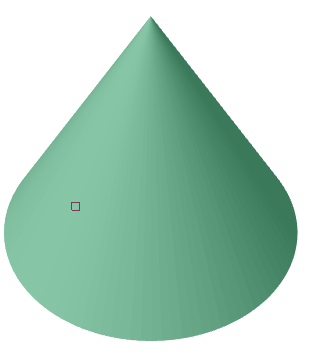
The command create 3D solid - Cone.
1. Call command "Cone".
2. Select the method for constructing the base:
· Base center (default) - the circle is built in the center and radius.
· 3Point - the circle is built at three points.
· RoundBaseBy2Point - build a circle at two points.
· Incircle round base - a circle is constructed along two tangents.
· Elliptical - an ellipse is built along the center, half-line and radius.
3. Specify the necessary parameters depending on the chosen method of building the foundation. The foundation will be built.
4. Choose a way to specify the height of the cone:
· Height - indicates the height in the drawing or on the command line.
· DistanceBy2Point - height is calculated by the specified two points in the drawing.
· Axis endpoint - height and direction are calculated at the specified point in the drawing, the first reference point is the center of the base.
· Upper radius - first the radius of the upper base is indicated, then the height is indicated.
5. Specify the required parameters depending on the selected method of specifying the height.
6. The cone will be built.
1. Grips change the height of the cone.
2. Grip move.
3. Grip change the radius of the upper base.
4. Grips change the radius of the lower base.
"3D solid". It is part of the body.
The following context menu commands are available:
· Rename (F2) - allows you to rename an object.
· Delete (Del) - removes an object and child objects from the tree and model space.
· ShowInDocument - focuses and highlights the object in the center of the model space.
· Rebuild - rearranges the object in the model space.
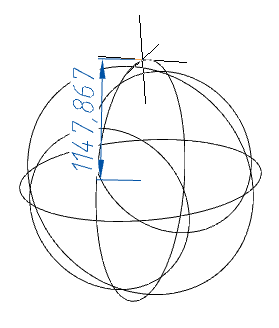
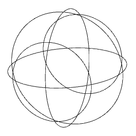
Main menu: 3D - Solid -  Sphere.
Ribbon: 3D Tools - 3D Solids - Sphere.
Toolbar: 3D Solid - Sphere.
Command line: 3DSPHERE.
The command create 3D solid - Sphere.
1. Call command "Sphere".
2. Choose a way to build a sphere:
· Center (default) - the circle is built in the center and radius.
· 3Point - the circle is built at three points.
· RoundBaseBy2Point - build a circle at two points.
· Incircle round base - a circle is constructed along two tangents.
3. Specify the necessary parameters depending on the selected construction method.
4. Sphere will be built.
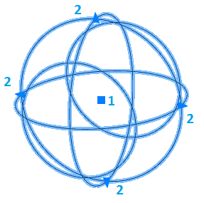
1. Grip move.
2. Grips change radius.
"3D solid". It is part of the body.
The following context menu commands are available:
· Rename (F2) - allows you to rename an object.
· Delete (Del) - removes an object and child objects from the tree and model space.
· ShowInDocument - focuses and highlights the object in the center of the model space.
· Rebuild - rearranges the object in the model space.
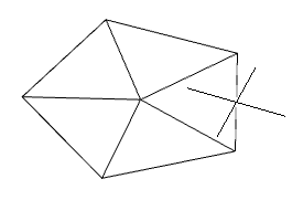
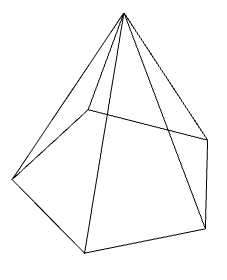
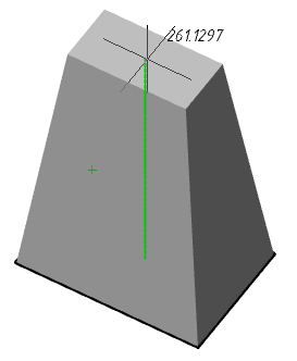
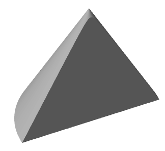
Main menu: 3D - Solid -  Pyramid.
Ribbon: 3D Tools - 3D Solids - Pyramid.
Toolbar: 3D Solid - Pyramid.
Command line: 3DPYRAMID.
The command create 3D solid - Pyramid.
1. Call command "Pyramid".
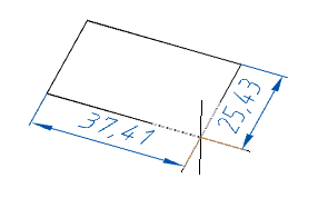
2. Select the method for constructing the base:
· Base center (default) - the base is built along the center and the radius of the inscribed or circumscribed circle.
· Edge - the base is constructed by indicating two points. The length of the edge of the base of the pyramid is the distance between two points.
· Sides - indication of the number of sides of the pyramid. After specifying the number of sides, the system again suggests choosing a construction method (p.2).
3. Specify the necessary parameters depending on the chosen method of building the foundation. The foundation will be built.
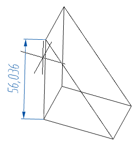
4. Choose a way to specify the height of the pyramid:
· Height - indicates the height in the drawing or on the command line.
· DistanceBy2Point - height is calculated by the specified two points in the drawing.
· Axis endpoint - height and direction are calculated at the specified point in the drawing, the first reference point is the center of the base.
· Upper radius - first the radius of the upper base is indicated, then the height is indicated.
5. Specify the required parameters depending on the selected method of specifying the height.
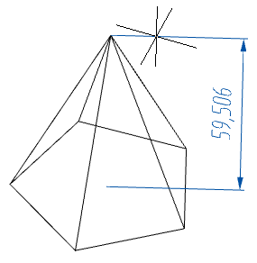
6. The pyramid will be built.
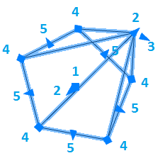
1. Grips moving.
2. Grips change height.
3. Grips change the radius of the upper base.
4. Grips change the radius of the lower base.
5. Grips change the radius of the lower base.
"3D solid". It is part of the body.
The following context menu commands are available:
· Rename (F2) - allows you to rename an object.
· Delete (Del) - removes an object and child objects from the tree and model space.
· ShowInDocument - focuses and highlights the object in the center of the model space.
· Rebuild - rearranges the object in the model space.
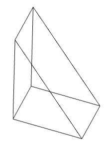
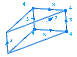
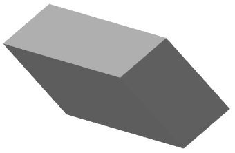
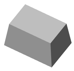
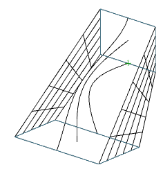
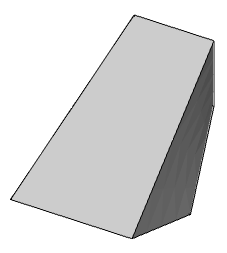
Main menu: 3D - Solid -  Wedge.
Ribbon: 3D Tools - 3D Solids - Wedge.
Toolbar: 3D Solid - Wedge.
Command line: 3DWEDGE.
The command create 3D solid - Wedge.
1. Call command "Wedge".
2. Select a point of reference (via the context menu or on the command line): "Corner" (default) or "Center".
· Corner - the sides of the wedge are counted from the specified point.
· Center - the sides are counted evenly from the center.
3. Specify the point of reference in the chosen way.
4. Select the method for constructing the base: "Corner" (default), "Cube" or "Length".
· Corner - a rectangle is constructed when specifying the second point.
· Cube - the length, width and height will be the same and after specifying the point a wedge will be built.
· Length - alternately indicate the length and width of the base.
5. Build the base in the chosen way.
6. Select the method of setting the height: "Height" (default) or "DistanceBy2Point".
· Height - the value of the height of the wedge is set in the drawing or in the command line.
· DistanceBy2Point - the value of the height of the wedge is set by specifying two points in the drawing.
7. Specify the height of the selected method.
8. Wedge will be built.
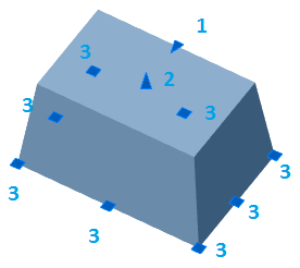
1. Grip move.
2. Grips wedge height changes.
3. Grips change the length or width of the base of the wedge.
4. Grips change the length and width of the base of the wedge.
"3D solid". It is part of the body.
The following context menu commands are available:
· Rename (F2) - allows you to rename an object.
· Delete (Del) - removes an object and child objects from the tree and model space.
· ShowInDocument - focuses and highlights the object in the center of the model space.
· Rebuild - rearranges the object in the model space.
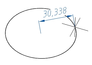
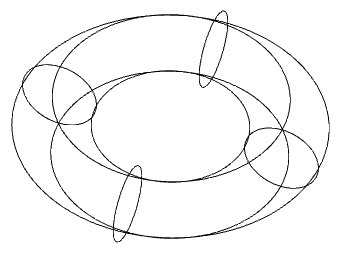
Main menu: 3D - Solid -  Torus.
Ribbon: 3D Tools - 3D Solids - Torus.
Toolbar: 3D Solid - Torus.
Command line: 3DTORUS.
The command create 3D solid - Torus.
1. Call command "Torus".
2. Select the method for constructing the axial radius:
· Center (default) - the circle is built in the center and radius.
· 3Point - the circle is built at three points.
· RoundBaseBy2Point - build a circle at two points.
· Incircle round base - a circle is constructed along two tangents.
3. Specify the necessary parameters depending on the chosen method of constructing the axial radius.
4. Choose a way to specify the cavity radius:
· Minor radius - indicates the radius in the drawing or in the command line.
· DistanceBy2Point - the radius is calculated from the indicated two points in the drawing.
5. Specify the required parameters depending on the selected method of specifying the cavity radius.
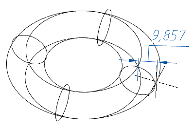
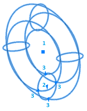
6. Torus will be built.
1. Grip move.
2. Grip changes in axial radius.
3. Grips change the radius of the cavity.
"3D solid". It is part of the body.
The following context menu commands are available:
· Rename (F2) - allows you to rename an object.
· Delete (Del) - removes an object and child objects from the tree and model space.
· ShowInDocument - focuses and highlights the object in the center of the model space.
· Rebuild - rearranges the object in the model space.
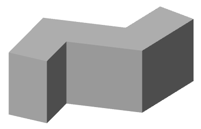
Main menu: 3D - Solid -  Polysolid.
Ribbon: 3D Tools - 3D Solids - Polysolid.
Toolbar: 3D Solid - Polysolid.
Command line: 3DPOLYSOLID.
The command create 3D solid - Polysolid.
1. Call command "Polysolid".
2. Configure polysolid parameters using the commands:
· Height - specifies the height of the polysolid.
· Width - specifies the width of the polysolid.
· Alignment - alignment is chosen when building: Left, Center or Right.
3. Select the build method:
· Polyline (default) - polysolid will be constructed in the same way as polyline.
· Object - the polysolid will be constructed by specifying the geometric object in the drawing, except for the spline and ellipse.
4. Build polysolid selected method of construction.
1. Grips height changes
2. Grips change the width.
3. Grips change the width and height.
4. Grips move end points of segments.
5. Grips moving segments.
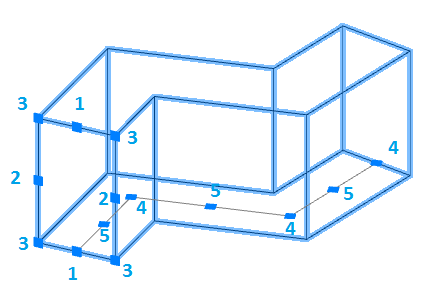
"3D solid". It is part of the body.
The following context menu commands are available:
· Rename (F2) - allows you to rename an object.
· Delete (Del) - removes an object and child objects from the tree and model space.
· ShowInDocument - focuses and highlights the object in the center of the model space.
· Rebuild - rearranges the object in the model space.
Main menu: 3D - Solid -  Interfere 3D solids.
Ribbon: 3D Tools - 3D Solids - Interfere 3D solids.
Toolbar: 3D Solid - Interfere 3D solids.
Command line: 3DINTERFERE.
1. Call command "Interfere 3D solids".
2. Select the first set of bodies. To complete the set selection, press "Enter".
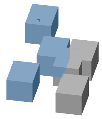
2. Select the second set of objects or select the command "check first set". When you select the second set, the overlap between sets, when selecting "check first set", overlaps within the set are analyzed.
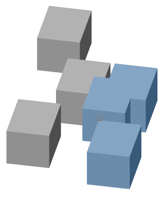
3. If overlaps exist, a dialog opens "Interference checking", otherwise - the command will end..
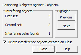
Interaction objects will be created and highlighted in the drawing.
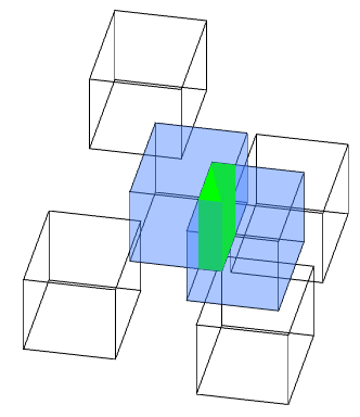
5. Perform floor analysis. In group "Interfering objects" shows the number of objects from the two sets and the number of pairs found. In group "Highlight" using the buttons "Previous" and "Next" highlight the interaction objects in the drawing. Switch "Delete interference objects on Close" deletes created interaction objects after closing the dialog "Interference checking".
6. Close dialog "Interference checking" on button "Close".
Main menu: 3D - 3D solid edit -  Extrude.
Ribbon: 3D Tools - 3D Solids - Extrude.
Toolbar: 3D Edit - Extrude.
Command line: EXTRUDE.
1. Call command "Extrude".
2. Select, if necessary, the type of object being created. Call the command "Mode" from the context menu or from the command line and select type: "Solid" or "Surface".
|
Solid |
Surface |
|
|
|
3. Select graphic primitives involved in extrusion. To complete the selection, press the key "Enter".
4. Indicate, if necessary, "Taper angle". Call the "Taper angle" command from the context menu or from the command line and enter the angle value. The command can be repeated several times.
5. Select the method for setting the extrusion depth:
· Height (default) - extrusion depth is set by the value in the command line or by the indication in the drawing.
· Direction - extrusion depth is set by two points in the drawing. The direction should not be coplanar or tangent to the plane of the object.
· Path - extrusion depth is set by specifying the trajectory. The path must not be coplanar or tangent to the plane of the object.
6. Set the extrusion depth using the selected method. The body or surface will be built.
1. Grip taper - allows you to change the angle of taper.
2. Grip Depth - allows you to change the depth of extrusion.
3. Grips section - handles change the shape of the section.
Main menu: 3D - 3D solid edit -  Revolve.
Ribbon: 3D Tools - 3D Solids - Revolve.
Toolbar: 3D Edit - Revolve.
Command line: REVOLVE.
1. Call command "Revolve".
2. Select, if necessary, the type of object being created. Call the command "Mode" from the context menu or from the command line and select type: "Solid" or "Surface".
|
Solid |
Surface |
|
|
|
3. Select rotating graphic primitives. To complete the selection, press the "Enter" key.
4. Select rotation axis:
2Points (default) - the axis is selected by sequential indication of two points.
Object - the axis is selected by specifying the object.
X/Y/Z - UCS axes are selected as the axis.
5. Change, if necessary, the direction of rotation. Call the command "Reverse" from the context menu or from the command line. Repeat the command the required number of times.
6. Change, if necessary, the initial angle of reference. Call the command "Specify start angle" from the context menu or from the command line. Enter the value of the starting angle. The value may be negative. Repeat the command the required number of times.
7. Specify the angle of rotation. The body or surface will be built.
1. Grip rotation angle - allows you to change the rotation angle.
2. Grip axis movement - allows you to change the position of the axis.
3. Grips section - handles change the shape of the section.
Main menu: 3D - 3D solid edit -  Loft.
Loft.
Ribbon: 3D Tools - 3D Solids - Loft.
Toolbar: 3D Edit - Loft.
Command line: LOFT.
1. Call command "Loft".
2. Select, if necessary, the type of object being created. Call the command "Mode" from the context menu or from the command line and select type: "Solid" or "Surface".
|
Solid |
Surface |
|
|
|
3. Specify the sections in sequence in the required order. To complete, press the "Enter" key. All sections must be either closed or open.
4. Set additional build parameters:
Cross-section only (default) - only sections are taken into account when calculating stretching.
Guides - when calculating the stretching, sections and additional guides are taken into account.
Path - when calculating the extrusion takes into account the section and the trajectory
5. Confirm the parameters on the "Enter" key. Loft will be built.
Section Grips - allow you to change the shape of sections.
Main menu: 3D - 3D solid edit -  Sweep.
Ribbon: 3D Tools - 3D Solids - Sweep.
Toolbar: 3D Edit - Sweep.
Command line: SWEEP.
1. Call command "Sweep".
2. Select, if necessary, the type of object being created. Call the command "Mode" from the context menu or from the command line and select type: "Solid" or "Surface".
|
Solid |
Surface |
|
|
|
3. Select graphic primitives involved in the shift. To complete the selection, press the "Enter" key.
4. If necessary, specify the alignment. Alignment can be perpendicular to the path or parallel to the section. Call the command "Alignment" from the context menu or from the command line and select the alignment option.
5. If necessary, specify a base point. The trajectory and section will be combined at the base point. Call the command "Base point" from the context menu or from the command line and specify the point on the section.
6. If necessary, specify the scale. Call the "Scale" command from the context menu or from the command line and specify the scale value.
7. If necessary, specify the twist angle. Call the "Twist" command from the context menu or from the command line and specify the angle value.
8. Select the trajectory.
9. Sweep will be built.
1. Grip move - allows you to move the 3D-body.
Main menu: 3D - 3D solid edit -  Slice.
Ribbon: 3D Tools - 3D Solids - Slice.
Toolbar: 3D Edit - Slice.
Command line: SLICE.
1. Call command "Slice".
2. Select the 3D body to be cut. To complete the selection, press the "Enter" key.
3. Select the method of defining the section plane:
2Points (default) - a cutting plane is constructed at two points perpendicular to the XY plane.
3Points - the cutting plane is defined by three points.
Planar object - A flat object is selected as the cutting plane.
4. Build a cutting plane in the chosen way.
5. Click the side you want to leave, or "Both".
6. The selected 3D bodies will be cut.
Main menu: 3D - 3D solid edit -  Section.
Ribbon: 3D Tools - 3D Solids - Section.
Toolbar: 3D Edit - Section.
Command line: SECTION.
The command creates a region object representing a 2D cross section of 3D objects, including 3D solids, surfaces, and meshes.
1. Prepare objects.
2. Call command "Section".
3. Select one or more 3D objects. Selecting multiple objects results in a separate area for each object.
4. Choose a method for specifying the plane:
· 3points (default) - Specifies a cutting plane by three points.
· Object - Aligns a cutting plane with a segment, circle, ellipse, circular or elliptical arc, 2D spline, or 2D polyline segment.
· Zaxis - Defines a section plane by specifying one point on that section plane and a second point on the z-axis or normal on that plane.
1. Point on the cutting plane. Sets the first point on the plane.
2. A point on the Z-axis (normal) on the plane. Sets the point that defines the axis perpendicular to the plane.
· View - Aligns the section plane with respect to the current view. After choosing the method, you should specify the point through which the plane will pass.
|
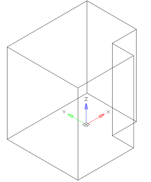
Point 0,0,0 |
|
|
|
Point 20,20,20 |
|
|
· XY - Aligns the section plane with the XY plane of the current UCS. After choosing the method, you should specify the point through which the plane will pass.
· YZ - Aligns the section plane with the YZ plane of the current UCS. After choosing the method, you should specify the point through which the plane will pass.
· ZX - Aligns the section plane with the ZX plane of the current UCS. After choosing the method, you should specify the point through which the plane will pass.
5. In accordance with the selected method, specify the section plane.
6. The area will be built.
1. Mode change grip: move mode, area change mode.
2. Nodal grips.
3. Movement grip.
Main menu: 3D - 3D solid edit -  Thicken.
Ribbon: 3D Tools - 3D Solids - Thicken.
Toolbar: 3D Edit - Thicken.
Command line: THICKEN.
The team works with "Surface" objects. The command sets the surface thickness.
1. Call command "Thicken".
2. Select surfaces to set the thickness. To complete the selection, press the "Enter" key.
3. Enter a new thickness. The value may be negative.
Main menu: 3D - 3D solid edit -  Presspull.
Ribbon: 3D Tools - 3D Solids - Presspull.
Toolbar: 3D Edit - Presspull.
Command line: PRESSPULL.
1. Call command "Presspull".
2. Select a face or limited area.
3. Use the "Multiple" context menu command if you need to specify multiple areas.
4. Set the extrusion distance. The value may be negative.
5. Extrusion of the face (closed area) will be performed.
Main menu: 3D - 3D solid edit -  Xedges.
Ribbon: 3D Tools - 3D Solids - Xedges.
Toolbar: 3D Edit - Xedges.
Command line: XEDGES.
1. Call command "Xedges".
2. Specify the 3D body from which you want to extract faces.
3. Faces will be extracted. The team will continue to work in a cyclical mode. To exit the cyclic mode, press the "Esc" key.
Main menu: 3D - 3D solid edit -  Offset edge.
Ribbon: 3D Tools - 3D Solids - Offset Edge.
Toolbar: 3D Edit - Offset edge.
Command line: OFFSETEDGE.
1. Call command "Offset edge".
2. Specify the edge of the 3D body on which the contour will be built.
3. Specify the shape of the contour corners. Call the "Corner" command from the context menu or from the command line and select "Round" or "Sharp". The radius of the round corners is equal to the size of the contour shift.
4. Specify the size of the contour shift. Call the command "Distance" from the context menu or from the command line and set the value.
5. Pick a point defining the side of the contour offset.
6. The contour of the face will be built.
Main menu: 3D - 3D solid edit -  Fillet edge.
Ribbon: 3D Tools - 3D Solids - Fillet Edge.
Toolbar: 3D Edit - Fillet edge.
Command line: FILLETEDGE.
1. Call command "Fillet edge".
2. Set the blend radius. Call the "Radius" command from the context menu or from the command line and specify the radius value.
3. Select the method for specifying the edges:
· Edge (default) - edges are selected by sequential selection.
· Loop - first one edge of the desired edge is selected, then the edge. All edges of the desired face are added to the set.
4. Specify edges in the selected way. All edges must have an adjacent face. To complete the selection, press the "Enter" key.

5. Check the resulting pairing. If necessary, change the radius.
6. Press the "Enter" key to confirm. Edge mate will be built.
Main menu: 3D - 3D solid edit -  Chamfer edge.
Ribbon: 3D Tools - 3D Solids - Chamfer Edge.
Toolbar: 3D Edit - Chamfer edge.
Command line: CHAMFEREDGE.
1. Call command "Chamfer edge".
2. Set the bevel distance. Call the "Distance" command from the context menu or from the command line and specify the distance value.
3. Select the method for specifying the edges:
· Edge (default) - edges are selected by sequential selection.
· Loop - first one edge of the desired edge is selected, then the edge. All edges of the desired face are added to the set.
4. Specify edges in the selected way. All edges must have an adjacent face. To complete the selection, press the "Enter" key.
5. Check the chamfer. If necessary, change the distance.
6. Press the "Enter" key to confirm. Chamfer edge will be built.
Main menu: 3D - 3D solid edit -  Solidedit.
Ribbon: 3D Tools - 3D Solids - Solid Editing.
Toolbar: 3D Edit - Solidedit.
Command line: SOLIDEDIT.
The team edits 3D solid, its faces and edges.
1. Call command "Solidedit".
2. Select the type of object to edit: Edge, Face, Body. For each type of object editing its menu of commands. To return the selection of the type of object being edited, press the "Enter" key.
3. Perform editing using the context menu commands:
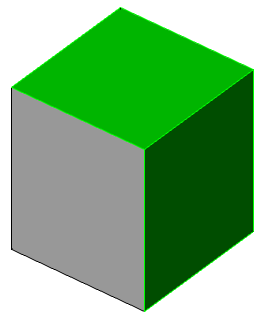
· Color (Edge, Face) - command sets new color.
· Select the faces (edges) on which you want to change the color. To complete the selection, press the "Enter" key. Open dialog "Select color".
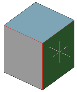
· In the "Select color" dialog box, define a new color in the way you like and click the "OK" button.
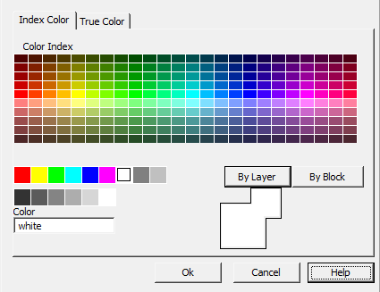
· New color will be applied.
|
Note: |
The change in the color of the edges can be seen on the visual styles with the edges shown. When you change the color of the face, the colors of its edges change. |
· Copy (Edge, Face) - allows you to copy a face (edge).
· Select the faces (edges) on which you want to change the color. To complete the selection, press the "Enter" key.
· Specify the base copy point.
· Specify the end point to which the faces (edges) will be copied.
· Copy will be made. The face is copied as a region, the edge is a segment.
· Imprint (Body) - command action is similar to command action "Imprint".
· Separate (body) - command shares a body that has several kinks.
Select body. The body will be divided in the presence of kinks.
4. Use the editing commands of the selected object type (p. 3) the required number of times. To return to the choice of the type of object being edited (p. 2), press the "Enter" key.
5. The "Solidedit" command works in a cyclic mode. To end the command, press the "Esc" key.
|
Important! |
This functionality requires a C3D 3D modeling engine. |
Main menu: 3D - Sheet metal -  Sheet metal.
Ribbon: 3D Tools - Sheet solids - Sheet metal.
Toolbar: Sheet metal - Sheet metal.
Command line: SMCREATE.
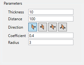
The shape of the sheet solid is determined by its sketch. The order in which the sheet solid is drawn depends on whether the sketch is closed or open.
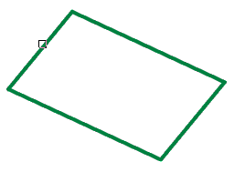
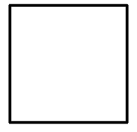
1. Draw a sketch: Closed or Open.
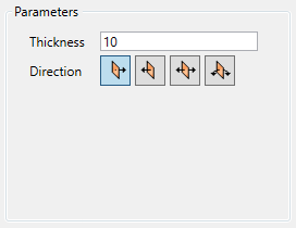
A closed sketch is extruded by a specified thickness in a direction perpendicular to its plane.
The following can act as a closed contour: closed polylines, circles, ovals.
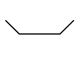
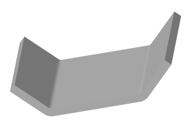
An open sketch is extruded to one or both sides by a specified distance; the thickness is added to the resulting surface. Sketch lines form flat sections of a sheet solid, arcs form bends of corresponding radius, and contour corners form bends with a user-defined inner radius.
The following can act as an open contour: open polylines with straight sections, lines, arcs.
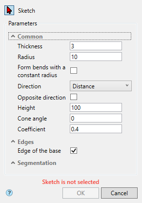
2. Call command Sheet solid. The "Sheet solid" dialog will open.
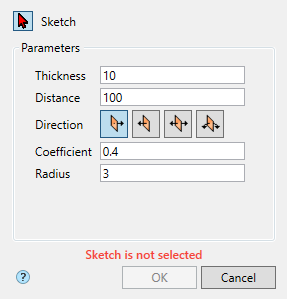
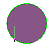
3. Select a sketch. A red cursor means that the sketch selection mode is on. If a sketch is not selected, the corresponding red "Sketch is not selected" is displayed.
If you need to replace the sketch (select another), re-enter the sketch selection mode by clicking the  "Sketch" button..
4. Specify the required parameters. Depending on the type of sketch, the composition of the parameters will change.
|
Open |
Close |
|
|
|
Confirm the action on the "OK" button. The sheet body will be built. If the "OK" button is grayed out, it means that the sketch was not selected or the parameters were set incorrectly. In the "3d History", a  "Sheet metal" object containing a sketch will be created with reference to an existing or new body.
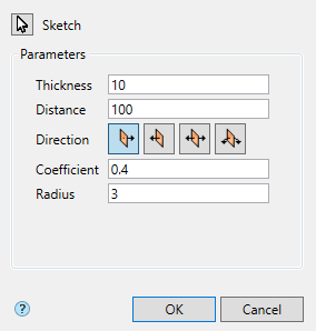
Button "Sketch" - turns on the sketch selection mode in the drawing.
Field "Thickness" - sheet body thickness.
Field "Distance" - sheet body length, if a closed sketch is specified, the field defines the thickness of the sheet body.
Field "Distance 2" - the length of the sheet body when the direction "Both directions" is selected, if a closed sketch is specified, the field determines the thickness of the sheet body.
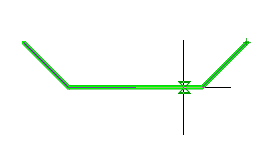
Direction select switch group:
·  Forward direction - directs the extrusion toward the positive direction of the axis perpendicular to the sketch plane.
·  Reverse direction - directs the extrusion toward the negative direction of the axis perpendicular to the sketch plane.
·  Both direction - directs the extrusion to both sides of the sketch plane, the distances are determined by the "Distance" and "Distance 2" parameters.
·  Middle plane - directs the extrusion to both sides of the sketch plane at the same distance.
Field "Coefficient" - neutral layer coefficient.
Field "Radius" - radius of connection of straight sections.
"Sheet metal". As part of the  body.
body.
The following context menu commands are available:
· Edit - calls the object for editing. The edit symbol appears to the right of the icon .
· Rename (F2) - allows you to rename an object.
· Delete (Del) - removes an object from tree and model space.
· Suppress - removes an object from model space.
· Unsuppress - restores the object in model space.
· ShowInDocument - focuses and highlights the subject in the center of model space.
· Rebuild - rebuilds an object in model space.
|
Important! |
This functionality requires a C3D 3D modeling engine. |
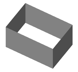
Main menu: 3D - Sheet metal -  Shell.
Ribbon: 3D Tools - Sheet solids - Shell.
Toolbar: Sheet metal - Shell.
Command line: SMSHELL.
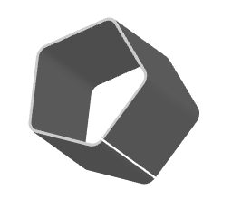
The sectional shape of the shell is determined by its sketch. A simple shell is formed by extruding a sketch in a direction perpendicular to its plane and adding thickness to the resulting surface. A sketch outline can be closed or open. If the contour is closed, then the shell is cut in height, the location and size of the gap are specified by the user. Various methods of trimming the shell edges are possible.
Sketch lines form flat portions of the shell, and contour corners form bends with a user-defined radius.
1. Draw a sketch. The sketch can be closed or open.
The following can act as a closed contour: closed polylines, circles, ovals.
An open contour can be: open polylines, lines, arcs, open splines.
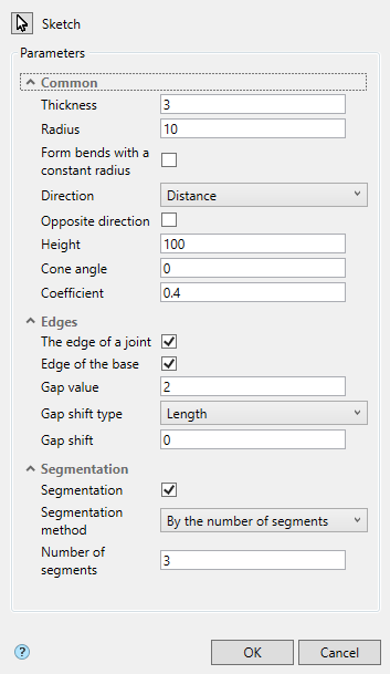
2. Call command "Shell". The "Shell" dialog will open.
3. Select a sketch. A red cursor means that the sketch selection mode is on. If a sketch is not selected, the corresponding red "Sketch is not selected" is displayed.
If you need to replace the sketch (select another), re-enter the sketch selection mode by clicking the "Sketch" button.
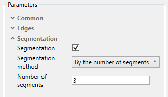
4. Specify the required parameters. Depending on the type of sketch, the composition of the parameters will change. For a contour with arcs, the segmentation options become available.
5. Confirm the action with the "OK" button. The sheet solid will be built. If the "OK" button is grayed out, it means that the sketch was not selected or the parameters were set incorrectly. In "3d History", a  "Shell" object containing the sketch will be created and snapped to an existing or new solid.
"Shell". As part of the body.
The following context menu commands are available:
· Edit - calls the object for editing. The edit symbol appears to the right of the icon .
· Rename (F2) - allows you to rename an object.
· Delete (Del) - removes an object from tree and model space.
· Suppress - removes an object from model space.
· Unsuppress - restores the object in model space.
· ShowInDocument - focuses and highlights the subject in the center of model space.
· Rebuild - rebuilds an object in model space.
|
Important! |
This functionality requires a C3D 3D modeling engine. |
Main menu: 3D - Sheet metal -  Ruled shellSheet metal.
Ribbon: 3D Tools - Sheet solids - Ruled shellа.
Toolbar: Sheet metal - Ruled shell.
Command line: SMRULEDSHELL.
The sectional shape of the shell is determined by its sketch. Two sketches are required for the construction of the ruled shell. A sketch outline can be closed or open. If the contour is closed, then the shell is cut in height, the location and size of the gap are specified by the user. Various methods of trimming the shell edges are possible.
1. Draw 2 sketches. The sketch can be closed or open.
The following can act as a closed contour: closed polylines, circles, ovals.
An open contour can be: open polylines, lines, arcs, open splines.
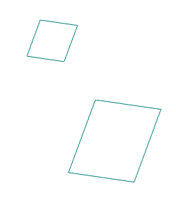
2. Call command "Ruled shell". The "Ruled shell" dialog will open.
3. Select 2 sketches. A red cursor means that the sketch selection mode is on. If no sketches are selected, the corresponding red text "Sketch 1, Sketch 2 are not selected" is displayed.
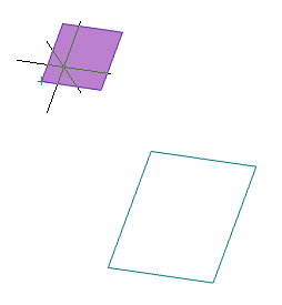
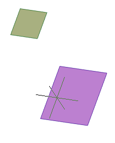
If you need to replace the sketch (select another), re-enter sketch selection mode by pressing the "Sketch 1" or "Sketch 2" button.
4. Specify the required parameters.
5. Confirm the action with the "OK" button. The ruled shell will be built. If the "OK" button is grayed out, it means that no sketches were selected or the parameters were set incorrectly. In "3d History", a  "Ruled shell" object containing sketches will be created and snapped to an existing or new solid.
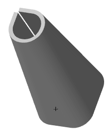
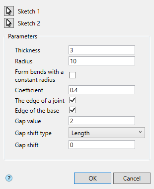
"Ruled shell". As part of the body.
The following context menu commands are available:
· Edit - calls the object for editing. The edit symbol appears to the right of the icon .
· Rename (F2) - allows you to rename an object.
· Delete (Del) - removes an object from tree and model space.
· Suppress - removes an object from model space.
· Unsuppress - restores the object in model space.
· ShowInDocument - focuses and highlights the subject in the center of model space.
· Rebuild - rebuilds an object in model space.
|
Important! |
|
This functionality requires a C3D 3D modeling engine. |
Main menu: 3D - Sheet metal -  Plate.
Ribbon: 3D Tools - Sheet solids - Plate.
Toolbar: Sheet metal - Plate.
Command line: SMPLATE.
A plate is a flat sheet metal piece glued to a sheet metal piece. The plate is formed by extruding a closed sketch. The extrusion depth can be arbitrary or equal to the thickness of the sheet metal.
1. Draw a closed loop sketch. The sketch must be positioned on the outer or inner planar face of the sheet solid.
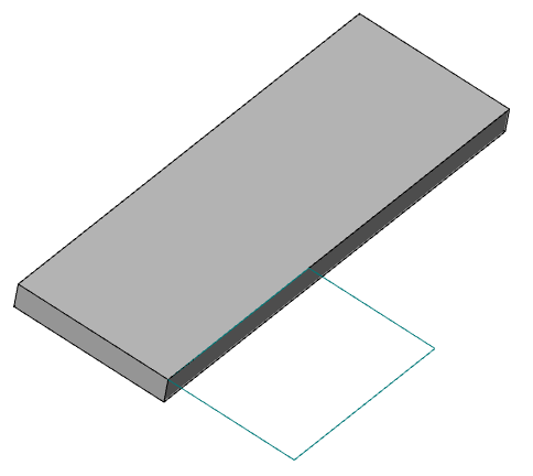
2. Call command "Plate". The "Plate" dialog will open.
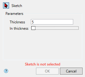
3. Select a sketch. A red cursor means that the sketch selection mode is on. If a sketch is not selected, the corresponding red "Sketch is not selected" is displayed.
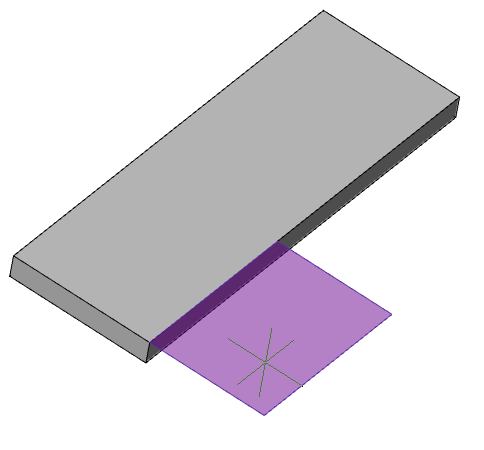
If you need to replace the sketch (select another), re-enter the sketch selection mode by clicking the "Sketch" button.
4. Specify the required parameters.
5. Confirm the action with the "OK" button. The sheet solid will be built. If the "OK" button is grayed out, it means that the sketch was not selected or the parameters were set incorrectly. In "3d History", a  "Plate" object containing the sketch will be created and snapped to an existing or new solid.
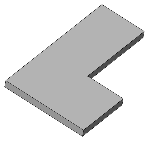
Button "Sketch" - turns on the sketch selection mode in the drawing.
Field "Thickness" - plate thickness.
Switch "In thickness" - when the switch is on, the thickness of the plate is equal to the thickness of the sheet, the "Thickness" field is hidden.
"Plate". As part of the body.
The following context menu commands are available:
· Edit - calls the object for editing. The edit symbol appears to the right of the icon .
· Rename (F2) - allows you to rename an object.
· Delete (Del) - removes an object from tree and model space.
· Suppress - removes an object from model space.
· Unsuppress - restores the object in model space.
· ShowInDocument - focuses and highlights the subject in the center of model space.
· Rebuild - rebuilds an object in model space.
|
Important! |
This functionality requires a C3D 3D modeling engine. |
Main menu: 3D - Sheet metal -  Bend along edge.
Ribbon: 3D Tools - Sheet solids - Bend along edge.
Toolbar: Sheet metal - Bend along edge.
Command line: SMEDGE.
A bend is created along one or more edges of the sheet metal. The edge (s) must be straight and belong to the outer or inner flat face of the sheet metal.
1. Call command "Bend along edge". The "Bend along edge" dialog will open.
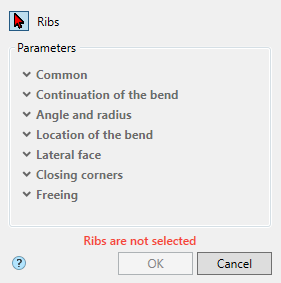
2. Select an edge. Red cursor means selection mode is on. If an edge is not selected, the corresponding red text "Ribs are not selected" is displayed.
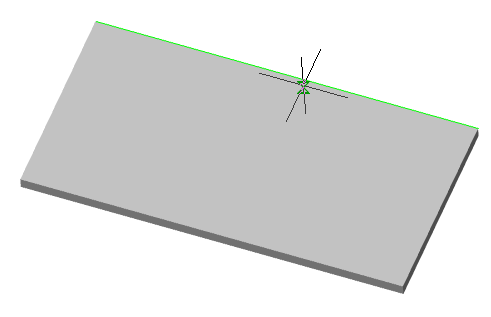
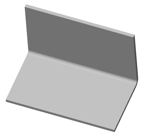
If you need to remove or add an edge, enter the selection mode again by pressing the"Ribs" button. Selected edges are highlighted in red, re-selecting an edge removes the selection.
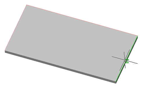
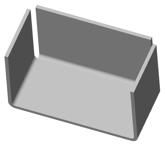
3. Specify the required parameters.
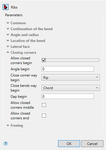
4. Confirm the action with the "OK" button. The bend will be built. If the "OK" button is inactive, it means that an edge was not selected or the parameters were set incorrectly. A  "Bend along edge" object will be created in "3d History" and will snap to an existing or new solid.
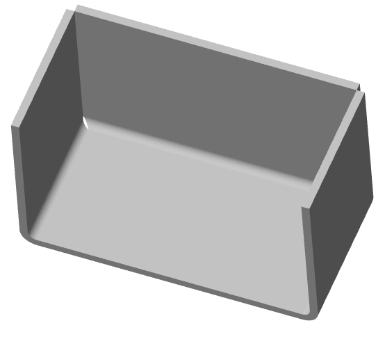
Button "Ribs" - turns on the ribs selection mode in the drawing.
Common
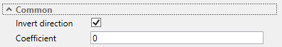
Continuation of the bend
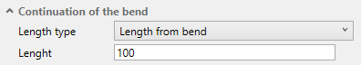
Angle and radius
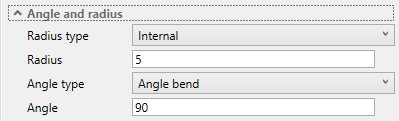
Location of the bend
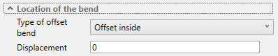
Lateral face
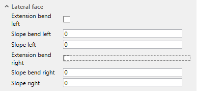
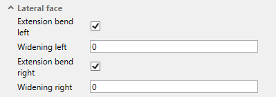
Closing corners
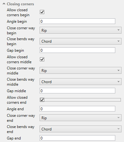
Freeing
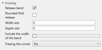
"Bend along edge". As part of the body.
The following context menu commands are available:
· Edit - calls the object for editing. The edit symbol appears to the right of the icon .
· Rename (F2) - allows you to rename an object.
· Delete (Del) - removes an object from tree and model space.
· Suppress - removes an object from model space.
· Unsuppress - restores the object in model space.
· ShowInDocument - focuses and highlights the subject in the center of model space.
· Rebuild - rebuilds an object in model space.
|
Important! |
|
This functionality requires a C3D 3D modeling engine. |
Main menu: 3D - Sheet metal -  Fold by sketch.
Ribbon: 3D Tools - Sheet solids - Fold by sketch.
Toolbar: Sheet metal - Fold by sketch.
Command line: SMJOINTBEND.
Fold by sketch - A multi-bend feature whose profile is defined by a contour in a sketch. The corners of a path in a sketch form bends with a user-defined inner radius.
1. Draw a sketch. The bend should be located along one straight edge or chain of straight edges of the sheet metal part. The edge is the bend line, and the containing face (outside or inside) is the base face of the bend.
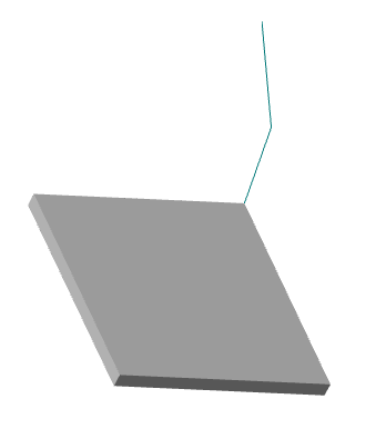
2. Call command "Fold by sketch". The "Fold by sketch" dialog will open.
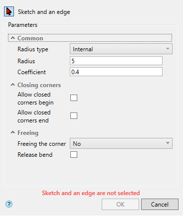
3. Select the sketch (path) and the edge of the sheet solid. Red cursor means selection mode is on.
If the path and edge of the sheet solid are not selected, the corresponding red "Sketch and an edge are not selected" text box is displayed.
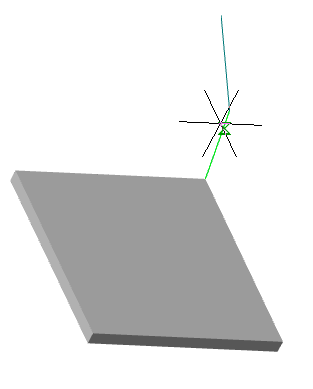
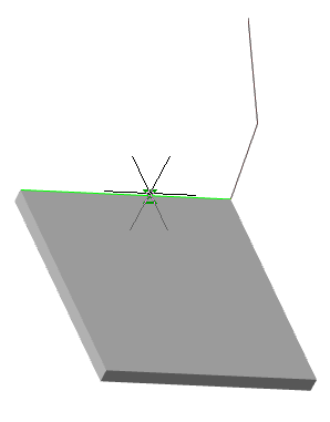
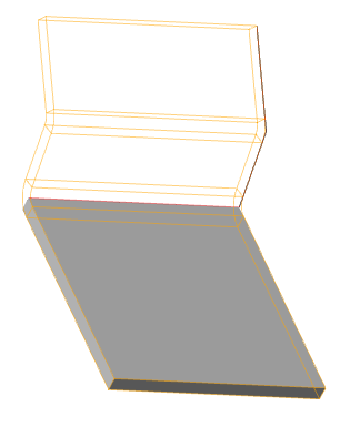
Pick multiple edges of the sheet body, if necessary.
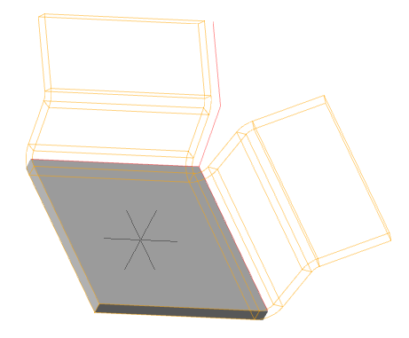
Press the"Sketch and an edge" button to complete your selection.
If you need to replace or add objects, enter the selection mode again by pressing the "Sketch and an edge" button.
4. Specify the required parameters.
5. Confirm the action with the "OK" button. The fold by sketch will be constructed. If the "OK" button is grayed out, it means that the path and edges were not selected or the parameters were set incorrectly. In "3d History", a  "Fold by Sketch" object is created that contains the sketch and snapped to an existing or new solid.
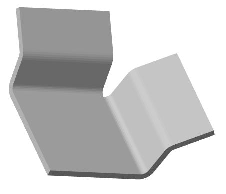
"Fold by sketch". As part of the body.
The following context menu commands are available:
· Edit - calls the object for editing. The edit symbol appears to the right of the icon .
· Rename (F2) - allows you to rename an object.
· Delete (Del) - removes an object from tree and model space.
· Suppress - removes an object from model space.
· Unsuppress - restores the object in model space.
· ShowInDocument - focuses and highlights the subject in the center of model space.
· Rebuild - rebuilds an object in model space.
|
Important! |
This functionality requires a C3D 3D modeling engine. |
Main menu: 3D - Sheet metal -  Bend along line.
Ribbon: 3D Tools - Sheet solids - Bend along line.
Toolbar: Sheet metal - Bend along line.
Command line: SMOVERSEG.
A sheet metal part can be bent in a straight line relative to the outer or inner flat face of that part. The specified line and face will be the bend line and bend base face.
1. Draw a bend line. The line can be a separate primitive or part of a sketch. The bend line must intersect the body completely.
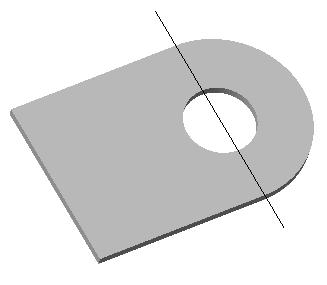
2. Call command "Bend along line". The "Bend along line" dialog will open.
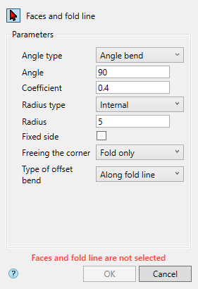
3. Select the face and bend line. Red cursor means selection mode is on. If faces and bend line are not selected, the corresponding red text "Faces and fold line are not selected" is displayed.
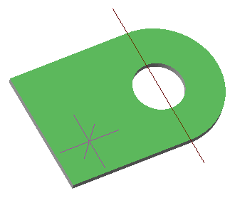
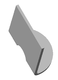
If you need to replace a face (select a different one), re-enter sketch selection mode by clicking the "Faces and fold line" button.
4. Specify the required parameters.
5. Confirm the action with the "OK" button. The bend will be constructed. If the "OK" button is inactive, it means that no objects were selected or the parameters were set incorrectly. In "3d History", a  "Bend along line" object containing the sketch will be created and snapped to an existing or new solid.
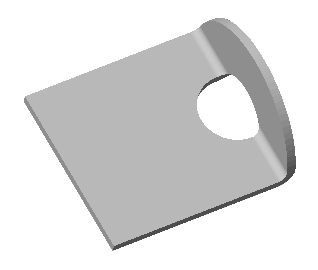
"Bend along line". As part of the body.
The following context menu commands are available:
· Edit - calls the object for editing. The edit symbol appears to the right of the icon .
· Rename (F2) - allows you to rename an object.
· Delete (Del) - removes an object from tree and model space.
· Suppress - removes an object from model space.
· Unsuppress - restores the object in model space.
· ShowInDocument - focuses and highlights the subject in the center of model space.
· Rebuild - rebuilds an object in model space.
|
Important! |
This functionality requires a C3D 3D modeling engine. |
Main menu: 3D - Sheet metal -  Jog.
Jog.
Ribbon: 3D Tools - Sheet solids - Jog.
Toolbar: Sheet metal - Jog.
Command line: SMJOG.
1. Draw a bend line. The line can be a separate primitive or part of a sketch. The bend line must intersect the body completely.
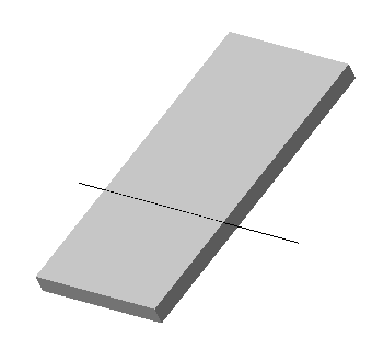
2. Call command "Jog". The "Jog" dialog will open
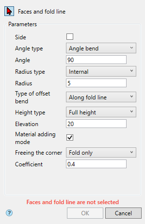
3. Select the face and bend line. Red cursor means selection mode is on. If faces and bend line are not selected, the corresponding red text "Faces and fold line are not selected" is displayed.
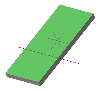

If you need to replace a face (select a different one), re-enter sketch selection mode by clicking the "Faces and fold line" button.
4. Specify the required parameters.
5. Confirm the action with the "OK" button. The Jog the line will be constructed. If the "OK" button is inactive, it means that no objects were selected or the parameters were set incorrectly. In "3d History", a  "Jog" object will be created containing the sketch and will snap to an existing or new body.
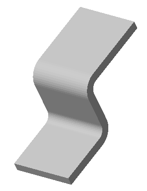
"Jog". As part of the body.
The following context menu commands are available:
· Edit - calls the object for editing. The edit symbol appears to the right of the icon .
· Rename (F2) - allows you to rename an object.
· Delete (Del) - removes an object from tree and model space.
· Suppress - removes an object from model space.
· Unsuppress - restores the object in model space.
· ShowInDocument - focuses and highlights the subject in the center of model space.
· Rebuild - rebuilds an object in model space.
|
Important! |
|
This functionality requires a C3D 3D modeling engine. |
Main menu: 3D - Sheet metal -  Closing corners.
Ribbon: 3D Tools - Sheet solids - Closing corners.
Toolbar: Sheet metal - Closing corners.
Command line: SMCORNER.
1. Call command "Closing corners". The "Closing corners" dialog will open.
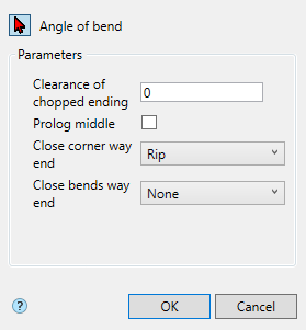
2. Select a bend angle. Red cursor means selection mode is on.
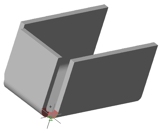
If you need to change the angle (select another), enter the selection mode again by pressing the "Angle of bend" button.
3. Specify the required parameters.
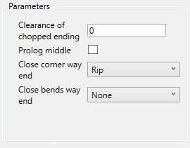
4. Confirm the action with the "OK" button. The closing corners will be constructed. If the "OK" button is inactive, it means that the corner was not selected or the parameters were set incorrectly. In the "3d History" object  "Closing corners" will be created, with a connection to an existing or new body.
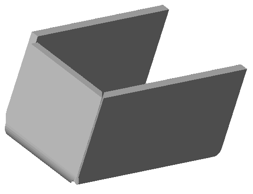
"Closing corners". As part of the body.
The following context menu commands are available:
· Edit - calls the object for editing. The edit symbol appears to the right of the icon .
· Rename (F2) - allows you to rename an object.
· Delete (Del) - removes an object from tree and model space.
· Suppress - removes an object from model space.
· Unsuppress - restores the object in model space.
· ShowInDocument - focuses and highlights the subject in the center of model space.
· Rebuild - rebuilds an object in model space.
|
Important! |
This functionality requires a C3D 3D modeling engine. |
Main menu: 3D - Sheet metal -  Hole.
Hole.
Ribbon: 3D Tools - Sheet solids - Hole.
Toolbar: Sheet metal - Hole.
Command line: SMHOLE.
1. Draw a closed sketch on one of the faces of the sheet solid.
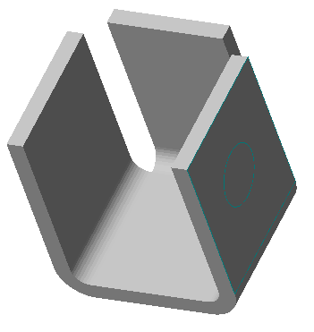
2. Call command "Hole". The "Hole" dialog will open.
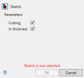
3. Select a sketch. A red cursor means that the sketch selection mode is on. If a sketch is not selected, the corresponding red "Sketch is not selected" is displayed.
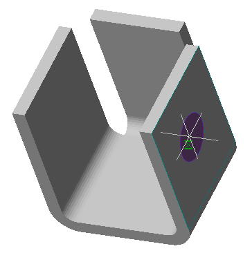
If you need to replace the sketch (select another), re-enter the sketch selection mode by clicking the "Sketch" button.
4. Specify the required parameters.
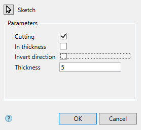
5. Confirm the action with the "OK" button. The hole will be built. If the "OK" button is grayed out, it means that the sketch was not selected or the parameters were set incorrectly. In "3d History", a  "Hole" object containing a sketch will be created and snapped to an existing or new solid.
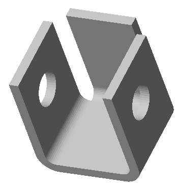
Button "Sketch" - turns on the sketch selection mode in the drawing.
Switch "Cutting" - defines the clipping area. When the switch is on, the area inside the sketch is cut out, when it is off - outside.
Switch "In thickness" - defines the depth of the cut. When the switch is on, the cut is made to the thickness of the sheet, when it is off, it is set independently.
Switch "Invert direction" - changes the direction of the cut.
Field "Thickness" - depth of cut, the field is active when the "In thickness" switch is off.
"Hole". As part of the body.
The following context menu commands are available:
· Edit - calls the object for editing. The edit symbol appears to the right of the icon .
· Rename (F2) - allows you to rename an object.
· Delete (Del) - removes an object from tree and model space.
· Suppress - removes an object from model space.
· Unsuppress - restores the object in model space.
· ShowInDocument - focuses and highlights the subject in the center of model space.
· Rebuild - rebuilds an object in model space.
|
Important! |
This functionality requires a C3D 3D modeling engine. |
Main menu: 3D - Sheet metal -  Unbend.
Ribbon: 3D Tools - Sheet solids - Unbend.
Toolbar: Sheet metal - Unbend.
Command line: SMUNBEND.
The command allows you to unbend sections of a sheet body.
1. Call command "Unbend". The "Unbend" dialog will open.
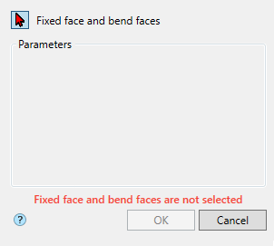
2. Select the face in the plane of which the bend will be performed and the bend adjacent to the face. Red cursor means selection mode is on. If no faces are selected, the corresponding red "Fixed face and bend faces are not selected" text is displayed.
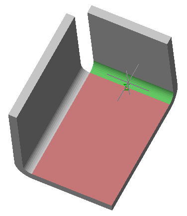
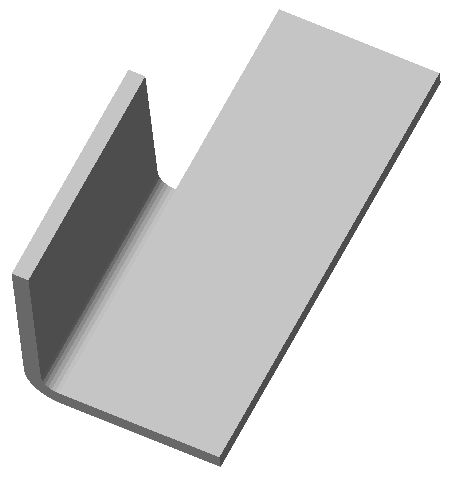
If you need to replace a face or add faces, re-enter selection mode by pressing the "Fixed face and bend faces" button. To confirm your choice, click on .
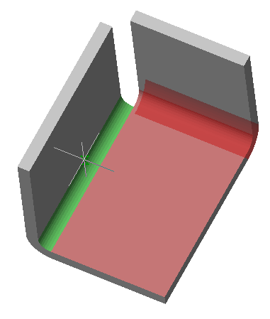
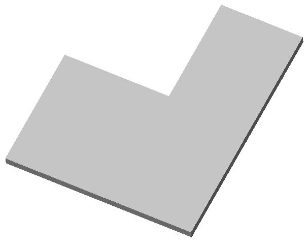
3. Confirm the action with the "OK" button. The sheet solid will be unbent. If the "OK" button is grayed out, then no faces were selected. An  "Unbend" object will be created in the "3d History", with a connection to an existing or new body.
Button "Fixed face and bend faces" - turns on the face selection mode in the drawing.
"Unbend". As part of the body.
The following context menu commands are available:
· Edit - calls the object for editing. The edit symbol appears to the right of the icon .
· Rename (F2) - allows you to rename an object.
· Delete (Del) - removes an object from tree and model space.
· Suppress - removes an object from model space.
· Unsuppress - restores the object in model space.
· ShowInDocument - focuses and highlights the subject in the center of model space.
· Rebuild - rebuilds an object in model space.
|
Important! |
This functionality requires a C3D 3D modeling engine. |
Main menu: 3D - Sheet metal -  Bend.
Bend.
Ribbon: 3D Tools - Sheet solids - Bend.
Toolbar: Sheet metal - Bend.
Command line: SMBEND.
The command allows you to bend previously unfolded sections of a sheet body.
1. Call command "Bend". The "Bend" dialog will open.
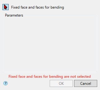
2. Select the main face to bend in the plane and the adjacent face (bend). Red cursor means selection mode is on. If no faces are selected, the corresponding red "Fixed face and faces for bending are not selected" text is displayed.
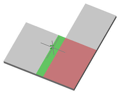
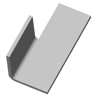
If you need to replace a face or add faces, re-enter selection mode by pressing the "Fixed face and faces for bending" button. To confirm your choice, click on .
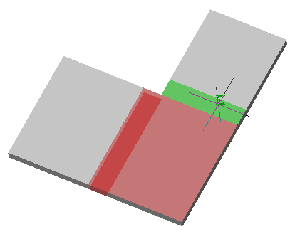
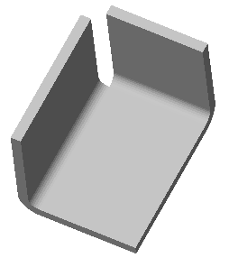
3. Confirm the action with the "OK" button. The sheet solid will be bent. If the "OK" button is grayed out, then no faces were selected. A  "Bend" object will be created in the "3d History", with a snap to an existing or new body.
Button "Fixed face and faces for bending" - turns on the face selection mode in the drawing.
"Bend". As part of the body.
The following context menu commands are available:
· Edit - calls the object for editing. The edit symbol appears to the right of the icon .
· Rename (F2) - allows you to rename an object.
· Delete (Del) - removes an object from tree and model space.
· Suppress - removes an object from model space.
· Unsuppress - restores the object in model space.
· ShowInDocument - focuses and highlights the subject in the center of model space.
· Rebuild - rebuilds an object in model space.
|
Important! |
This functionality requires a C3D 3D modeling engine. |
Main menu: 3D - Sheet metal -  Flatten.
Ribbon: 3D Tools - Sheet solids - Flatten.
Toolbar: Sheet metal - Flatten.
Command line: SMFLATTEN.
The command allows you to create a flat pattern of a sheet body.
1. Call command "Flatten". The "Flatten" dialog will open.
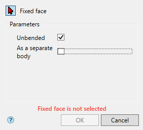
2. Select the face to unfold relative to. Red cursor means selection mode is on. If no face is selected, the corresponding red text "Fixed face is not selected" is displayed.
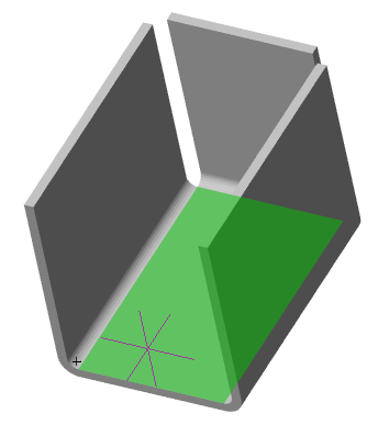
If you need to replace a face, re-enter selection mode by pressing the "Fixed face" button.
3. Confirm the action with the "OK" button. The flatten will be built. If the "OK" button is grayed out, then no face has been selected. In the "3d History" object  "Flatten" will be created, with reference to an existing or new body.
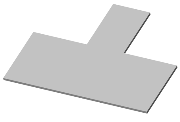
Button "Fixed face" - turns on the face selection mode in the drawing.
Switch "Unbended" - controls the sweep state.
Switch "As a separate body" - creates a separate body.
"Flatten". As part of the body.
The following context menu commands are available:
· Edit - calls the object for editing. The edit symbol appears to the right of the icon .
· Rename (F2) - allows you to rename an object.
· Delete (Del) - removes an object from tree and model space.
· Suppress - removes an object from model space.
· Unsuppress - restores the object in model space.
· ShowInDocument - focuses and highlights the subject in the center of model space.
· Rebuild - rebuilds an object in model space.
|
Important! |
|
This functionality requires a C3D 3D modeling engine. |
Main menu: 3D - Sheet metal -  Stamp.
Ribbon: 3D Tools - Sheet solids - Stamp.
Toolbar: Sheet metal - Stamp.
Command line: SMSTAMP.
1. Draw a closed sketch on the face of the sheet body.
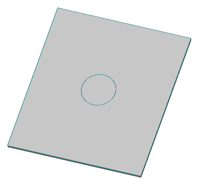
2. Call command "Stamp". The "Stamp" dialog will open.
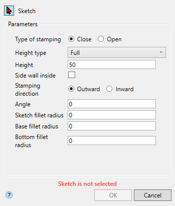
3. Select a sketch. A red cursor means that the sketch selection mode is on. If a sketch is not selected, the corresponding red "Sketch is not selected" is displayed.
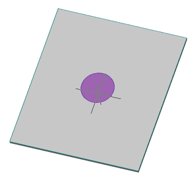
If you need to replace the sketch (select another), re-enter the sketch selection mode by clicking the "Sketch" button.
4. Specify the required parameters.
5. Confirm the action with the "OK" button. The stamp will be created. If the "OK" button is grayed out, it means that the sketch was not selected or the parameters were set incorrectly. In "3d History", a  "Stamp" object containing the sketch will be created and snapped to an existing or new solid.
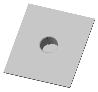
"Stamp". As part of the body.
The following context menu commands are available:
· Edit - calls the object for editing. The edit symbol appears to the right of the icon .
· Rename (F2) - allows you to rename an object.
· Delete (Del) - removes an object from tree and model space.
· Suppress - removes an object from model space.
· Unsuppress - restores the object in model space.
· ShowInDocument - focuses and highlights the subject in the center of model space.
· Rebuild - rebuilds an object in model space.
|
Important! |
This functionality requires a C3D 3D modeling engine. |
Main menu: 3D - Sheet metal -  Jalousie.
Ribbon: 3D Tools - Sheet solids - Jalousie.
Toolbar: Sheet metal - Jalousie.
Command line: SMJALOUSIE.
1. Sketch on the face of the sheet body. Lines are used as sketches for the punch. The sketch must be completely within the base face of the feature.
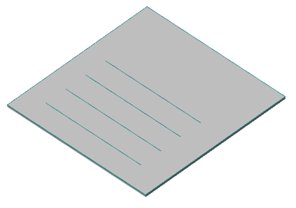
2. Call command "Jalousie". The "Jalousie" dialog will open.
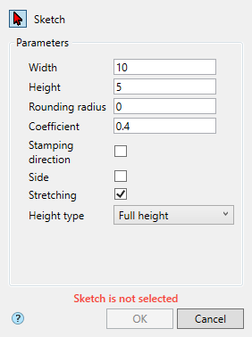
3. Select a sketch. A red cursor means that the sketch selection mode is on. If a sketch is not selected, the corresponding red "Sketch is not selected" is displayed.
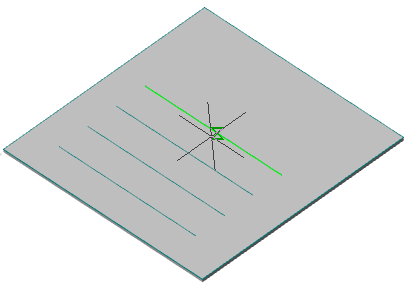
If you need to replace the sketch (select another), re-enter the sketch selection mode by clicking the "Sketch" button.
4. Specify the required parameters.
5. Confirm the action with the "OK" button. The punch will be created. If the "OK" button is grayed out, it means that the sketch was not selected or the parameters were set incorrectly. If the preview does not show the punch, then the parameters are incorrect. In "3d History", a  "Jalousie" object containing a sketch is created and snapped to an existing or new solid.
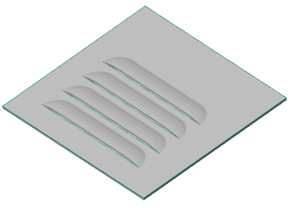
"Jalousie". As part of the body.
The following context menu commands are available:
· Edit - calls the object for editing. The edit symbol appears to the right of the icon .
· Rename (F2) - allows you to rename an object.
· Delete (Del) - removes an object from tree and model space.
· Suppress - removes an object from model space.
· Unsuppress - restores the object in model space.
· ShowInDocument - focuses and highlights the subject in the center of model space.
· Rebuild - rebuilds an object in model space.
|
Important! |
This functionality requires a C3D 3D modeling engine. |
Main menu: 3D - Sheet metal -  Bead.
Bead.
Ribbon: 3D Tools - Sheet solids - Bead.
Toolbar: Sheet metal - Bead.
Command line: SMBEAD.
1. Sketch on the face of the sheet body. A sketch can contain multiple primitives.
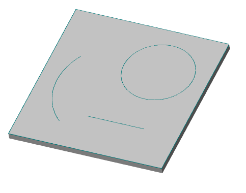
2. Call command "Bead". The "Bead" dialog will open.

3. Select a sketch. A red cursor means that the sketch selection mode is on. If a sketch is not selected, the corresponding red "Sketch is not selected" is displayed.
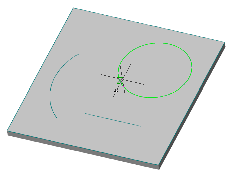
If you need to replace the sketch (select another), re-enter the sketch selection mode by clicking the "Sketch" button.
4. Specify the required parameters.
5. Confirm the action with the "OK" button. The bend will be created. If the "OK" button is grayed out, it means that the sketch was not selected or the parameters were set incorrectly. In "3d History", a  "Bead" object containing a sketch will be created and referenced to an existing or new solid.
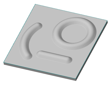
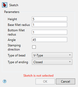
"Bead". As part of the body.
The following context menu commands are available:
· Edit - calls the object for editing. The edit symbol appears to the right of the icon .
· Rename (F2) - allows you to rename an object.
· Delete (Del) - removes an object from tree and model space.
· Suppress - removes an object from model space.
· Unsuppress - restores the object in model space.
· ShowInDocument - focuses and highlights the subject in the center of model space.
· Rebuild - rebuilds an object in model space.
|
Important! |
This functionality requires a C3D 3D modeling engine. |
Main menu: 3D - Sheet metal -  Rib.
Rib.
Ribbon: 3D Tools - Sheet solids - Rib.
Toolbar: Sheet metal - Rib.
Command line: SMRIB.
1. Call command "Rib". The "Rib" dialog will open.
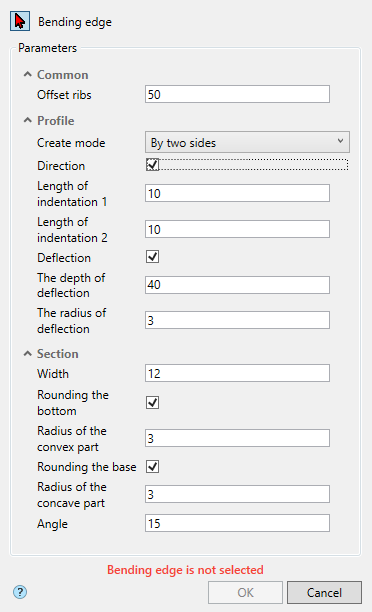
2. Select an edge at the bend location. Red cursor means selection mode is on. If the edge is not selected, the corresponding red text "Bending edge is not selected" is displayed.
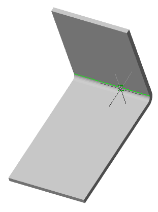
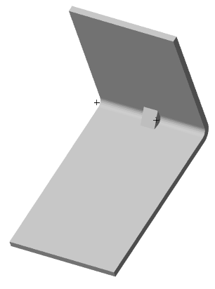
If you need to replace an edge (select another), enter the selection mode again by pressing the "Bending edge" button.
3. Specify the required parameters.
4. Confirm the action with the "OK" button. The rib will be built. If the "OK" button is inactive, it means that the object was not selected or the parameters were set incorrectly. In the "3d History" object  "Rib" will be created, with a connection to an existing or new body.
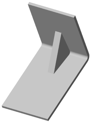
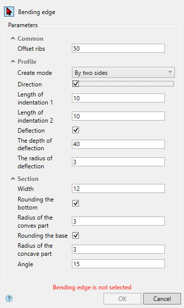
"Rib". As part of the body.
The following context menu commands are available:
· Edit - calls the object for editing. The edit symbol appears to the right of the icon .
· Rename (F2) - allows you to rename an object.
· Delete (Del) - removes an object from tree and model space.
· Suppress - removes an object from model space.
· Unsuppress - restores the object in model space.
· ShowInDocument - focuses and highlights the subject in the center of model space.
· Rebuild - rebuilds an object in model space.
|
Important! |
This functionality requires a C3D 3D modeling engine. |
Main menu: 3D - Sheet metal -  Flanging.
Ribbon: 3D Tools - Sheet solids - Flanging.
Toolbar: Sheet metal - Flanging.
Command line: SMFLANGING.
1. Call command "Flanging". The "Flanging" dialog will open.
2. Select the edges on the sheet body. The red cursor means that the selection mode is enabled. If an edge is not selected, the corresponding red caption "Not selected: Edges" is displayed.
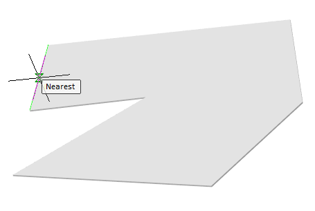
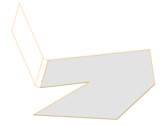
Select the required number of ribs. To cancel the selection, reselect the edge.
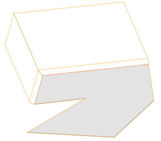
To complete the selection, select the "Finish" context menu command. If you need to replace the edge (select another one), enter the selection mode again by pressing the "Ribs" button.
3. Specify the required parameters on the form.
5. Confirm the action on the "OK" button. The flanging will be built. If the "OK" button is inactive, it means that the object was not selected or the parameters were set incorrectly. In the "3D History" the "Flanging" object will be created, with reference to an existing or new part.
3D History
"Flanging". As part of the body.
The following context menu commands are available:
· Edit - calls the object for editing. The edit symbol appears to the right of the icon .
· Rename (F2) - allows you to rename an object.
· Delete (Del) - removes an object from tree and model space.
· Suppress - removes an object from model space.
· Unsuppress - restores the object in model space.
· ShowInDocument - focuses and highlights the subject in the center of model space.
· Rebuild - rebuilds an object in model space.
Main menu: 3D -3D Features -  3D Align.
Ribbon: 3D Tools - Solid Editing - 3D Align.
Toolbar: 3D - 3D Align.
Command line: 3DALIGN.
A tool for pairing surfaces, curves, or points in model space.
|
Note: |
Information about the alignment does not fall into the "3DHistory". |
1. Call command "3D Align".
2. Specify the objects that you want to align. To complete the selection, press the "Enter" key. The dialog "3D Align" will open.
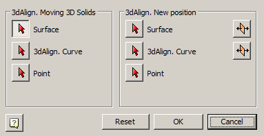
3. Use the "3D Align" dialog to select the locations in one of three ways:
· Surface to Surface. The surface can be a face of a part or a plane. In this method, the surface is adjacent to the surface. When using the button  "Change Direction" the direction of aligned objects is changing.
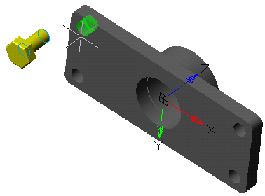
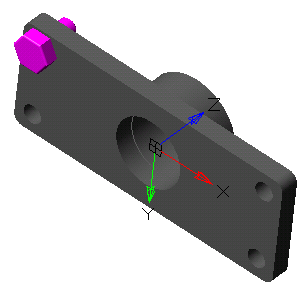
· Curve to Curve. The axis can be an edge of the part or an axis. In this method, the selected axes are combined. When using the button "Change Direction" the direction of aligned objects is changing.
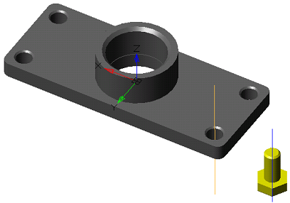
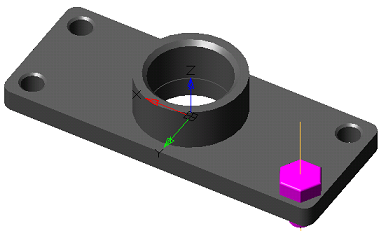
· Point to point. In this method, points are combined.
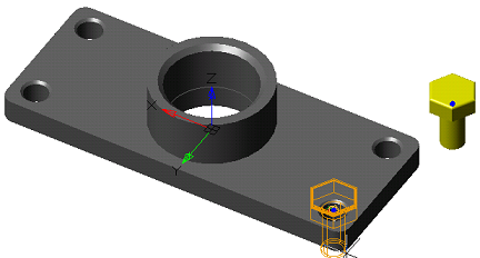
4. When all the locations have been selected, click "OK". Alignment will be performed.
Manipulators allow you to manipulate the 3D model: move, rotate or change the scale.
There are two ways to use manipulators:
1. Force a call using the appropriate commands: 3D Move, 3D Rotate, 3D Scale.
2. Automatic call of the configured manipulator when selecting a 3D model (the call does not work in 2D Wireframe mode).
The DEFAULTMANIPULATOR system variable (default keyer) is responsible for configuring the automatic call of the manipulator.
Manipulators and how to install them:
1. Move Manipulator
Main menu: 3D - 3D Features -  Move Manipulator.
Ribbon: 3D Tools - Manipulators - 3D Move Manipulator.
Toolbar: 3D Transformations - Move Manipulator.
Command line: DEFAULTMANUPULATOR1.
Command line: DEFAULTMANUPULATOR - set to 1 or select "Move manipulator".
2. Rotate Manipulator
Main menu: 3D -3D Features -  Rotate Manipulator.
Ribbon: 3D Tools - Manipulators - 3D Rotate Manipulator.
Toolbar: 3D Transformations - Rotate Manipulator.
Command line: DEFAULTMANUPULATOR2.
Command line: DEFAULTMANUPULATOR - set to 2 or select "Rotate manipulator".
3. Scale Manipulator
Main menu: 3D -3D Features -  Scale Manipulator.
Ribbon: 3D Tools - Manipulators - 3D Scale Manipulator.
Toolbar: 3D Transformations - Scale Manipulator.
Command line: DEFAULTMANUPULATOR3.
Command line: DEFAULTMANUPULATOR - set to 3 or select "Scale manipulator".
4. No Manipulator
Main menu: 3D - 3D Features -  No Manipulator.
Ribbon: 3D Tools - Manipulators - Without Manipulator.
Toolbar: 3D Transformations - No Manipulator.
Command line: DEFAULTMANUPULATOR4.
Command line: DEFAULTMANUPULATOR - set to 4 or select "No manipulator".
Main menu: 3D - 3D Features -  3D Move.
Ribbon: 3D Tools - Solid Editing - 3D Move.
Toolbar: 3D - 3D Move.
Toolbar: 3D Transform - 3D Move.
Command line: 3DMOVE.
Tool for moving part in model space.
|
Important! |
Without the 3D module for "Nonparametric solid" objects, the manipulator works in demo mode, i.e. there will be no actual movement. |
1. Call command "3D Move".
2. Select part in model space or in "3D History". The sketch part should not be tied to one of the main planes of the model. The selected parts are highlighted in green, and the selected ones in yellow. You can select multiple parts in one operation. After completing the selection, press the "Enter" key or the "Enter" command from the context menu.
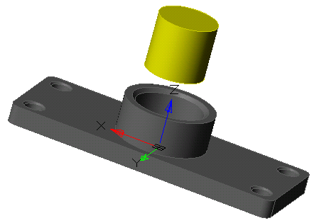
3. Select the axis or plane along which the movement will occur.
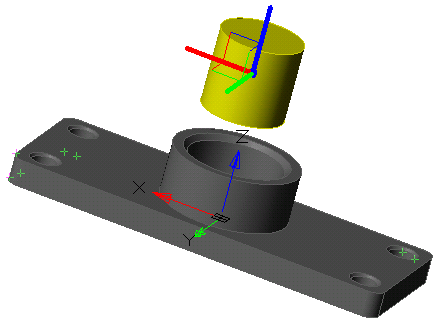
4. Forward movements of the mouse move part along the selected axis (plane). You can also enter the value of the navigation from the keyboard.
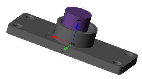
5. Repeat the movement as many times as necessary (p.3-p.4). When the transfer is complete, press the "Enter" key or the "Enter" command from the context menu.
Main menu: 3D - 3D Features -  3D Rotate.
Ribbon: 3D Tools - Solid Editing - 3D Rotate.
Toolbar: 3D - 3D Rotate.
Toolbar: 3D Transform - 3D Rotate.
Command line: 3DROTATE.
Tool for rotating part in model space.
|
Important! |
Without the 3D module for "Nonparametric solid" objects, the manipulator works in demo mode, i.e. there will be no actual movement. |
1. Call command "3D Rotate".
2. Select the rotating part in the model space or in the "3D History". The sketch part should not be tied to one of the main planes of the model. The selected parts are highlighted in green, and the selected ones in yellow. You can select multiple parts in one operation. When the selection is complete, press the "Enter" key or the "Enter" command from the context menu.
3. Select the base point on the rotated part. This point will be the center of rotation around the selected axis.
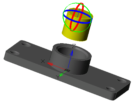
4. Select the axis along which the rotation will occur.
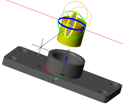
5. In the forward movements of the mouse, rotate the part along the selected axis. You can also enter the value of the rotation angle from the keyboard.
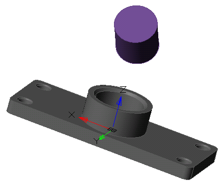
6. Repeat the rotation as many times as necessary (p.3-p.5). When the transfer is complete, press the "Enter" key or the "Enter" command from the context menu.
Main menu: 3D - 3D Features -  3D Scale.
Ribbon: 3D Tools - Solid Editing - 3D Scale.
Toolbar: 3D - 3D Scale.
Toolbar: 3D Transform - 3D Scale.
Command line: 3DSCALE.
3D scaling allows you to resize selected objects and subobjects along an axis or a plane or to scale objects uniformly.
|
Important! |
The command applies only to objects "3D Solid" and "Polyface Mesh" |
|
Important! |
Without the 3D module for "Nonparametric solid" objects, the manipulator works in demo mode, i.e. there will be no actual movement. |
1. Call command "3D Scale";
2. Select objects that require scaling;
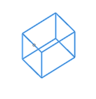
3. Press the key "Enter (Space)";
4. Specify the base point of scaling;
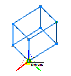
5. Specify a scale axis or a scale plane;
· Same scale. Click the area near the top of the 3D Scaling. The internal part of all axes stands out. Scaling will be performed evenly across all three axes.
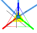
· Limitation of scaling by the position of the plane. Click between the parallel lines located between the axes defining the plane. Scaling will be done in two axes. This operation is only for Mesh, it is not applicable to 3D Solid and surfaces.
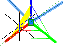
· Scale limiting by axis position. Click the Axis. Scaling will be done on one axis. This operation is only for Mesh, it is not applicable to 3D Solid and surfaces
6. Set the scale (on the drawing or on the command line), objects will be scaled;
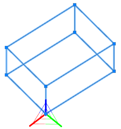
7. Repeat steps 4-6 as many times as necessary. To end the command, press "Esc (Space)".
Main menu: 3D - 3D Features -  3D Rectangular Pattern.
Ribbon: 3D Tools - Solid Editing - 3D Rectangular Array.
Toolbar: 3D - 3D Rectangular Pattern.
Command line: 3DRECTPAT.
Tool for creating an array in one or two directions.
1. Call command "3D Rectangular Pattern". Open dialog "3D Rectangular Pattern".
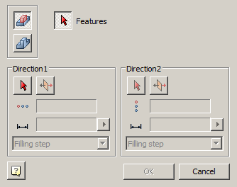
2. Select the type of objects involved in the creation of the array:
·  Array of features. An array of elements will refer to the original body.
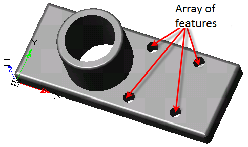
|
Note: |
Chamfers and fillets can not be received by the array as separate elements; You can not make an array of chamfers or fillets! Chamfers and fillets can be used only as a part of bodies. |
·  Array of bodies. The whole body goes to the array, a new body with an element will be created "McRectangularPatternFeature".
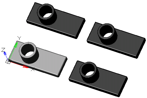
3. Select elements to create an array.
4. Adjust the array parameters, or take them from the sample array.
Parameters from sample array:
· Press button  "Get parameters from sample array".
· Specify sample array.
· The created array will be passed: direction, quantity, distance and type of distance.
Specifying parameters yourself:
· Select the first direction of the array. The axis of the GCS, the working axis or the edge of any body can be used as a direction. The phantom of the created array is highlighted in orange.
· Invert if necessary the direction of the layout of elements with the button "Flip direction".
· Specify the number of copies in the input field  "Count elements".
· Enter the distance in the input field  "Distance". To the right of the input field is a button
  "Measure distance", allowing you to take a value from the drawing.
· Select distance type:
· Filling step - sets the distance between each element in the array.
· Filling range - sets the distance between the extreme elements in the array.
· Repeat steps for the second direction, if the array is built in two directions.
5. Press button "OK". An array will be created based on the selected items. In the "3D History" an object appears "McRectangularPatternFeature".
"McRectangularPatternFeature". It is part of the body. When creating an array from the elements of the source body, the object "McRectangularPatternFeature" falls into the composition of the original body. When creating an array from the source body, a new body is created, object "McRectangularPatternFeature" falls into the new body.
The object "McRectangularPatternFeature" includes: folder "Elements" with a list of source elements or folder "Solids" with a list of source bodies, and links  "Occurrence", showing the elements of the array in model space.
The following commands of the object's context menu are available "McRectangularPatternFeature":
· Edit - opens the editing dialog "3D Rectangular Pattern".
· Rename (F2) - allows you to rename a pattern.
· Delete (Del) - removes a pattern from the tree and model space.
· Suppress - removes a pattern from model space.
· Unsupress - restores a pattern in model space.
· ShowInDocument - focuses and highlights a pattern in the center of model space.
· Rebuild - rebuilds an object in model space.
Main menu: 3D - 3D Features -  3D Circular Pattern.
Ribbon: 3D Tools - Solid Editing - 3D Polar Array.
Toolbar: 3D - 3D Circular Pattern.
Command line: 3DCIRCPAT.
Tool for creating an array of elements or bodies around a certain axis.
1. Call command "3D Circular Pattern". Open dialog "3D Circular Pattern".
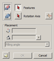
2. Select the type of objects involved in the creation of the array:
· Array of features. An array of elements will refer to the original part.
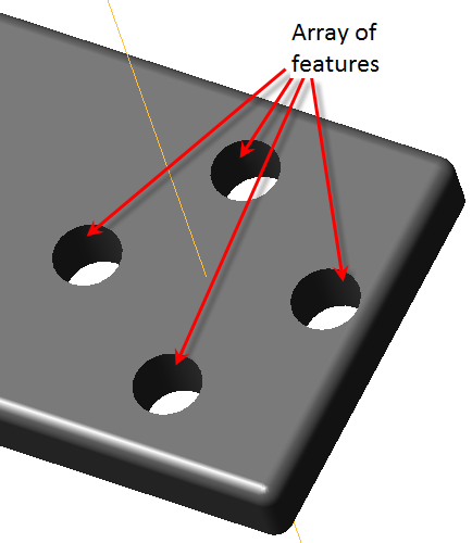
|
Note: |
Chamfers and fillets can not be received by the array as separate elements; You can not make an array of chamfers or fillets! Chamfers and fillets can be used only as a part of bodies. |
· Array of bodies. he whole body goes to the array, a new body with an element will be created  "McCircularPatternFeature".
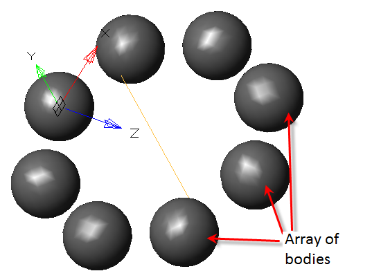
3. Select elements to create an array.
4. Adjust the array parameters, or take them from the sample array.
Parameters from sample array:
· Press button "Get parameters from sample array".
· Specify sample array.
· The following will be passed to the created array: axis of rotation, direction, amount, angle and type of filling.
Specifying parameters yourself:
· Select the axis. As an axis, the GCS axis, the working axis or the edge of any body can be used. Orange color is highlighted by a phantom of the created array.
|
Important! |
The edges of the bodies involved in the creation of the array cannot be used as an axis. It turns out that one edge participates in several closed shells, and the parts to be combined can never exactly touch each other. Existing 3D kernels process this data incorrectly, so such an array is likely to be built erroneously. In order to correct, you can use the auxiliary axis, slightly shifted in parallel from the desired one, for example, by 1 μm. |
· Invert if necessary the direction of the layout of elements with the button "Flip direction". By default, the layout is clockwise.
· Enter the number of copies in the input field  "Count of items".
· Specify the angle in the input field  "Angle for items". To the right of the input field is the button "Measure angle", allowing you to take a value from the drawing.
· Specify the type of filling:
· Filling angle - sets the value of the fill angle between the extreme elements in the array.
· Spacing angle - sets the value of the step between each element in the array.
5. Press button "OK". An array will be created based on the selected elements. In the "3D History" object appears "McCircularPatternFeature".
"McCircularPatternFeature".It is part of the part. When creating an array from the elements of the source body, the object "McCircularPatternFeature" falls into the composition of the original body. When creating an array from the source body, a new body, object "McCircularPatternFeature" falls into the new body.
The object"McCircularPatternFeature" includes: folder "Elements" with a list of source elements or folder "Solids" with a list of source bodies, and links "Occurrence", showing array elements in the model space.
The following commands of the object's context menu are available "McCircularPatternFeature":
· Edit - opens the editing dialog "3D Circular Pattern".
· Rename (F2) - allows you to rename an array.
· Delete (Del) - removes an array from the tree and model space.
· Suppress - removes an array from model space.
· unsuppress - restores an array in model space.
· ShowInDocument - focuses and highlights the array in the center of the model space.
· Rebulid - rebuilds the object in model space.
Main menu: 3D - 3D Features -  3D Fillet.
Ribbon: 3D Tools - Solid Editing - Fillet Edge.
Toolbar: 3D - 3D Fillet.
Command line: 3DFILLET.
Tool for creating different kinds of fillets.
1. Call command "3D Fillet". The "3D Fillet" dialog will be opened.
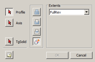
2. Define the rib selection method using the "Edge chain".
|
|
|
|
|
|


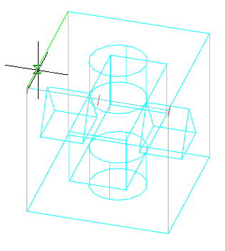
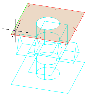
3. Select the edges. During the selection process, the rounding phantoms will be visible in the modeling environment.
4. Specify the radius. To the right of the radius input field is the button "Measure radius", allowing to take the value from the drawing.
5. Press the "OK" key. Fillets will be built. In the "3D History" in the part will be an object  "McFilletFeature".
"McFilletFeature". It is found in the part.
The following shortcut menu commands are available:
· Edit - opens the editing dialog "3D Fillet".
· Rename (F2) - allows you to rename a fillet.
· Delete (Del) - removes fillet from tree and model space.
· Suppress - removes fillet from model space.
· Unsuppress - restores the fillet in the model space.
· ShowInDocument - focuses and highlights the fillet at the center of the model space.
· Rebuild - rebuilds an object in model space.
Main menu: 3D - 3D Features -  3D Chamfer.
Ribbon: 3D Tools - Solid Editing - Chamfer Edge.
Toolbar: 3D - 3D Chamfer.
Command line: 3DCHAMFER.
Tool for creating all kinds of chamfers.
1. Call command "3D Chamfer". Open dialog "3D Chamfer".
|
Note: |
Simultaneously, on two or more bodies the facet can not be built. You need to call the |
2. In the "3D Chamfer" dialog, select the method for creating the chamfer and specify the required parameters, depending on the method:
·  Equal distances from both faces - it makes it possible to build a chamfer in one dimension - length. The angle is automatically equal to 45°.
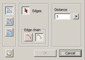
· Define the rib selection method using the "Edge chain".
|
|
|
|
|
|
· Select the edges. During the selection process, the chamfering phantoms will be visible in the simulation environment.
· Enter the distance. To the right of the distance input field is the button "Measure distance", allowing to take the value from the drawing.
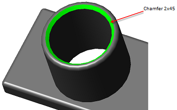
·  Distance and angle from specify face - it is possible to construct a facet by the angle and length of the selected face.
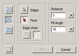
· Select face.
· Determine the method for selecting edges using the switch group "Edge chain".
· Select the edges of this face. During the selection process, the chamfering phantoms will be visible in the modeling environment.
· Enter the distance. To the right of the distance input field is the button "Measure distance", allowing to take the value from the drawing.
· Enter the angle. To the right of the distance input field is the button "Measure angle", allowing to take the value from the drawing.
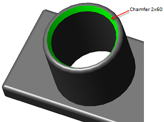
·  Two distances -it is possible to construct a facet on two distances from the edge.
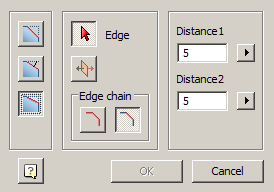
· Determine the method for selecting edges using the switch group "Edge chain".
· Select the edges. During the selection process, the chamfering phantoms will be visible in the modeling environment.
· Enter the distances. To the right of the distance input fields are the buttons "Measure distance", allowing to take the value from the drawing.
· If necessary, invert the distance values using the button  "Invert values".
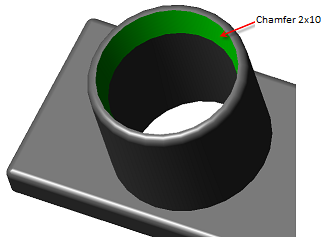
3. Press button "OK". Chamfers will be built. In the "3D History" in the part will be an object  "McChamferFeature".
"McChamferFeature".It is found in the part.
The following shortcut menu commands are available:
· Edit - opens the editing dialog "3D Chamfer".
· Rename (F2) - allows you to rename a chamfer.
· Delete (Del) - removes the chamfer from the tree and model space.
· Suppress - removes a chamfer from the model space.
· Unsuppress - restores a chamfer in model space.
· ShowInDocument - focuses and highlights the chamfer in the center of the model space.
· Rebuild - rebuilds an object in model space.
Main menu: 3D - 3D Features -  3D Thread.
Ribbon: 3D Tools - Details - Thread.
Toolbar: 3D - 3D Thread.
Command line: 3DTHREAD.
The command sets the thread on the selected cylindrical section of the 3D body.
1. Call command "3D Thread". The "3D Thread" dialog will open. When the command is running, the visual style will be set to "Fast shaded".
2. Specify "Thread face". The face should be cylindrical.
3. Make thread settings in the "3D Thread" dialog and click the "OK" button.
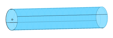
4. The thread will be built. The visual style will revert to the original. In "3D History", a "Thread" object is added to the body.
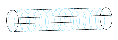
Called in the "3D History" from the context menu of the "Thread" object.
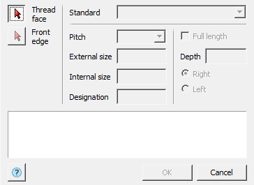
The editing dialog is divided into parts:
· Face selection panel

Button "Thread face" - allows you to select a cylindrical face to thread onto.
Button "Front edge" - allows you to select the thread origin face.
· Standart
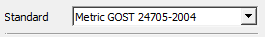
Combobox "Standart" - allows you to select the thread standard.
· Thread Parameter Panel
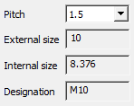
Combobox "Pitch" - allows you to select the thread pitch. The list of options depends on the diameter of the cylindrical face and the selected standard.
Field "External size" - shows the outer diameter of the thread. The field is not editable.
Field "Internal size" - shows the inside diameter of the thread. The field is not editable.
Field "Designation" - shows the thread designation. The input field is not editable.
· Panel for setting thread length and direction
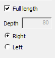
Checkbox "Full length" - controls the setting of the thread length. If the switch is on - the length of the thread is determined by the length of the cylindrical face, off - the length of the thread is specified in the "Depth" input field.
Field "Depth" - specifies the thread length.
Group switch for thread direction - "Right" or "Left".
· Dashboard
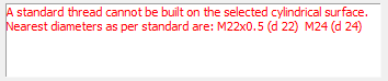
Shows errors and remarks when setting up threads.
 "Thread". As part of the body.
The following context menu commands are available:
· Edit - the command opens the thread editing dialog "3D Thread".
· Rename (F2) - allows you to rename an object.
· Delete (Del) - removes object and child objects from tree and model space.
· Suppress - removes object and child objects from model space.
· Unsuppress - restores the object in model space.
· ShowInDocument - focuses and highlights the subject in the center of model space.
· Rebuild - rebuilds an object in model space.
Main menu: 3D - 3D Features -  3D Mirror.
Ribbon: 3D Tools - Solid Editing - 3D Mirror.
Toolbar: 3D - 3D Mirror.
Command line: 3DMIRROR.
Tool for creating a reflection of an element or a body with respect to the plane of reflection. The command works only with parametric solids.
1. Call command "3D Mirror". Open dialog "3D Mirror".
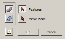
2. In the "3D Mirror" dialog, select the type of reflection:
· Array of features. Reflected body elements and reflection will refer to the original body.
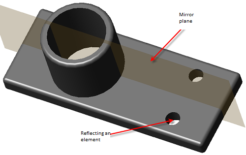
· Array of bodies. The whole body is reflected, a new body with an element will be created  "McMirrorFeature".
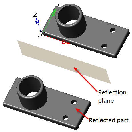
3. Select elements or body, depending on the type of reflection selected.
4. Select the reflection plane. It can be the plane of the coordinate system, the working plane or the face of any body. When selecting a reflection plane, a phantom reflective appears.
5.Press button "OK". Reflection will be created based on the selected items. In the "3D History" an object appears "McMirrorFeature".
"McMirrorFeature". It is part of the body. When the elements of the original body are reflected, the object "McMirrorFeature" falls into the composition of the original body. When the original body is reflected, a new body, object "McMirrorFeature" falls into the new body.
The object "McMirrorFeature" includes: folder "Elements" with a list of source elements or folder "Solids" with a list of source bodies, and two links "Occurrence",showing in the model space the finding of the original elements and reflected.
The following commands of the object's context menu are available "McMirrorFeature":
· Edit - opens the editing dialog "3D Mirror".
· Rename (F2) - allows you to rename an object.
· Delete (Del) - removes an object from the tree and model space.
· Suppress - removes the mirrored object from the model space.
· Unsuppress - restores a mirrored object in model space.
· ShowInDocument - focuses and highlights the mirrored object in the center of model space.
· Rebuild - rebuilds an object in model space.
Ribbon: 3D Tools - Solid Editing -  Union.
Toolbar: 3D - Union.
Command line: UNION.
The tool allows you to combine parametric objects or 3D solidities.
1. Call command "Union";
2. Specify the merge objects;
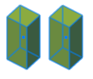
3. Press the "Enter (Space)" key;
4. Union will be made. All selected objects become one object. In "3D History", the first selected body will display an object "Union", containing all selected bodies except the first.
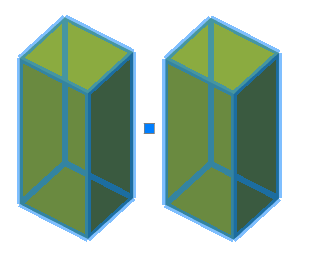
|
Note: |
If the objects were selected before the "Union" command is called, the union will be automatically generated immediately after the call. |
"Union". It is part of the parent part, contains parts that are combined with the parent part.
The following shortcut menu commands are available:
· Rename (F2) - allows you to rename an association.
· Delete (Del) - removes the union and its associated objects from the tree and model space.
· Suppress - suppresses the union. With the parts included in the union, you can treat as individual objects.
· Unsupress - restores the union.
· ShowInDocument - focuses and highlights the incoming bodies in the center of model space.
· Rebuild - rebuilds an object in model space.
Ribbon: 3D Tools - Solid Editing -  Intersection.
Toolbar: 3D - Intersect.
Command line: INTERSECT.
The tool allows you to create an object based on the intersection of several objects. That is, the new object will be the joint intersected area.
1. Call command "Intersect";
2. Specify intersecting objects;
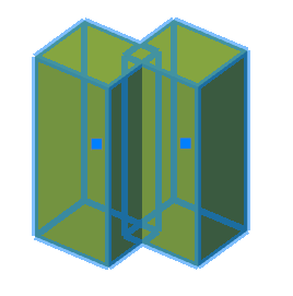
3. Press the "Enter (Space)" key;
4. A new object based on the intersection will be created. In "3D History", the first selected body will display an object "Intersect", containing all selected bodies except the first.
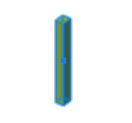
|
Note: |
If the objects were selected before the "Intersect" command is called, the intersection will be automatically generated immediately after the call. |
"Intersect". It is part of the parent part, contains parts that intersect with the parent part.
The following shortcut menu commands are available:
· Rename (F2) - allows you to rename an intersection.
· Delete (Del) - removes the intersection and associated objects from the tree and model space.
· Suppress - suppresses the intersection action. With bodies entering the intersection, you can treat both as individual objects.
· Unsuppress - restores the intersection action.
· ShowInDocument - focuses and highlights the faces obtained as a result of the intersection, in the center of the model space.
· Rebuild - rebuilds an object in model space.
Ribbon: 3D Tools - Solid Editing -  Subtraction.
Toolbar: 3D - Subtract.
Command line: SUBTRACT.
The tool allows you to create an object based on the selected objects by subtracting one of the others (the objects are divided into those from which the subtraction will be made and those that will subtract).
1. Call command "Subtract";
2. Specify the objects from which the subtraction will be made;
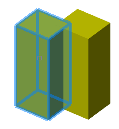
3. Specify the objects that will be subtracted;
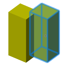
4. Press the "Enter (Space)" key;
5. A new object will be created. If the number of bodies from which a subtraction of more than one was made, then in "3D History" in the first subtrahend body appears object "Subtract", containing all subtrahend bodies except the first. In the same body, an object will appear "Intersect", containing all subtractive bodies.
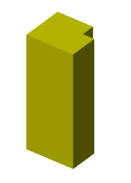
|
Note: |
If the objects from which the subtraction will be made were selected before the "Subtract" command is called, then the command immediately proceeds to the selection of subtracting objects. |
"Subtract". It is part of the parent body, contains bodies that are subtracted from the parent.
The following shortcut menu commands are available:
· Rename (F2) - allows you to rename subtraction.
· Delete (Del) - removes subtraction and related objects from the tree and model space.
· Suppress - suppresses the subtraction action. With the parts included in the subtraction, one can treat both as individual objects.
· Unsuppress - restores the subtraction action.
· ShowInDocument - focuses and highlights the edges obtained as a result of subtraction, in the center of the model space.
· Rebuild - rebuilds an object in model space.
Main menu: 3D - 3D Features -  Add work plane.
Ribbon: 3D Tools - Solid Editing - Add work plane.
Toolbar: 3D - Add work plane.
Command line: ADDWPL.
A tool that allows you to add a new plane to the model space.
1. Call command "Add work plane".
2. Choose how to build a plane from the context menu or command line:
· select object - the construction of a plane by choosing a face or a part edge.
· 3PT - plane construction by three points.
· 2LN - the construction of a plane along two axes (segments can also be axes for constructing a plane).
· WPL_NORM2CURV - the construction of the plane is normal to the curve. To build, you must specify a curve and a point.
· WPL_NORM2SURF - the construction of a plane normal to the surface. To build, you must specify a surface and a point.
· LPANG - the construction of the plane along the axis, plane and angle. The angle is measured from the selected plane counterclockwise.
· PLOFS - plot the plane at a distance from the selected one.
3. Select the required objects according to the chosen method of plotting the plane. To facilitate the selection of "the main coordinate system selection items", commands will be available in the context menu:
· Origin - Selects the point of intersection of the main axes of coordinates.
· X, Y, Z - Selects axes of the main coordinate system.
· XY, YZ, ZX - Selects the planes of the main coordinate system.
4. The "Work Plane" object will be created and added to "3D History".
Does not have individual properties.
Moving grip - serves to move the plane in the model space. It is recommended not to use.
Work plane. Can be located in the root of the tree and enter the structure of objects "Part".
The following shortcut menu commands are available:
· Rename (F2) - allows you to rename a plane.
· Delete (Del) - removes the plane and related objects from the tree and model space.
· Create 2d-sketch - calls the command "Add planar sketch". The drawing sketch plane is not necessary.
· Hide - hides the mapping of the plane in model space.
· Show - shows the mapping of the plane in model space.
· Fix - fixes a plane in model space. An anchor label is added to the plane icon. The command is available if the plane does not belong to the body.
· Unfix - Defines a plane in model space. The command is available if the plane does not belong to the body.
· ShowInDocument - focuses the plane in the center of the model space. The command is available when the plane is displayed.
· Rebuild - rebuilds the object in model space.
Main menu: 3D - 3D Features -  Add work axis.
Ribbon: 3D Tools - Solid Editing - Add work axis.
Toolbar: 3D - Add work axis.
Command line: ADDWA.
A tool that allows you to add a new axis to the model space.
1. Call command "Add work axis".
2. Choose how to draw an axis from the context menu or command line:
· select object - the construction of the plane by the choice of the edge of the part.
· 2PT - plane construction by two points.
· AXIS - the construction of an axis along a segment: edges, axes of symmetry, free geometry.
· 2PLN - the construction of an axis on the line of intersection of two planes.
· WA_NORM2CURV - the construction of the axis is normal to the curve. To build, you must specify a curve and a point.
· WA_NORM2SURF - the construction of an axis normal to the surface. To build, you must specify a surface and a point.
3. Select the required objects according to the selected axis construction method. To facilitate the selection of "the main coordinate system selection items", commands will be available in the context menu:
· Origin - Selects the point of intersection of the principal axes of coordinates.
· X, Y, Z - Selects axes of the main coordinate system.
· XY, YZ, ZX - Selects the planes of the main coordinate system.
4. The "Work axis" object will be created and added to "3D History".
Does not have individual properties.
Moving grip - serves to move the axis in the model space. If the axis belongs to the body, it moves with it.
Work axis. It can be located in the root of the tree and be part of objects "Part".
The following shortcut menu commands are available:
· Rename (F2) - allows you to rename an axis.
· Delete (Del) - removes the axis and related objects from the tree and model space.
· Hide - hides the axis map in model space.
· Show - shows the display of the axis in model space.
· Fix - fixes the axis in the model space. An anchor label is added to the axis icon. The command is available if the axis does not belong to the body.
· Unfix - Defines an axis in model space. The command is available if the axis does not belong to the body.
· ShowInDocument - focuses the axis in the center of the model space. The command is available when the axis is displayed.
· Rebuild - rebuilds the object in model space.
Main menu: 3D - 3D Features -  Add work point.
Ribbon: 3D Tools - Solid Editing - Add work point.
Toolbar: 3D - Add work point.
Command line: ADDWPT.
A tool that allows you to add a new point to the model space.
1. Call command "Add work point".
2. Choose how to build a point from the context menu or command line:
· select object - the construction of a working point by choosing a point of the part.
· VERTEX - the construction of a point along the existing working point, the vertex of the body, the middle of the part's rib, the characteristic points of free geometry, and so on.
· CENTER - construction of the point at the central point of the element.
· 2CRV - the construction of a point at the intersection of two curves.
· CRVSURF - the construction of a point in the intersection of a curve and a surface.
· 3PLN - the construction of a point in the intersection of three planes.
3. Select the required objects according to the selected way of constructing the point. To facilitate the selection of the "main coordinate system selection items", the following commands will be available in the context menu:
· Origin - Selects the point of intersection of the principal axes of coordinates.
· X, Y, Z - Selects axes of the main coordinate system.
· XY, YZ, ZX - Selects the planes of the main coordinate system.
4. The "Work point" object will be created and added to "3D History".
Does not have individual properties.
Moving grip - serves to move a point in the model space. If the point belongs to the part, it moves with it.
Work point. Can be located in the root of the tree and enter the structure of objects "Part".
The following shortcut menu commands are available:
· Rename (F2) - allows you to rename a point.
· Delete (Del) - removes a point and related objects from the tree and model space.
· Hide - hides the display of a point in the model space.
· Show - shows the display of a point in the model space.
· Fix - fixes a point in the model space. An anchor label is added to the point icon. The command is available if the point does not belong to the part.
· Unfix - defixes a point in model space. The command is available if the point does not belong to the part.
· ShowInDocument - focuses the point in the center of the model space. The command is available when the point is displayed.
· Rebuild - rebuilds an object in model space.
|
Important! |
To use this functionality, the 3D modeling engine C3D is required. |
Main menu: 3D - 3D Features -  Mate 3D Constraint.
Ribbon: 3D Tools - 3D Constraint - Mate 3D Constraint.
Toolbar: 3D - Mate 3D Constraint.
Command line: 3DMATE.
The command allows you to impose a 3D constraint "Mate" on objects.
1. Call command "Mate 3D Constraint";
|
Important! |
When applying a constraint, at least one solid must be unfixed. |
2. Select the geometry of the first solid (plane, edge, or point);
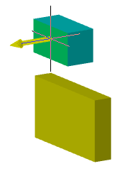
3. Select the geometry of the second solid (plane, edge, or point);
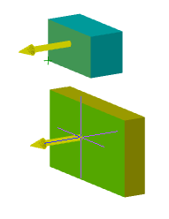
|
Note: |
Alignment is performed along the normals of the selected geometry. When you select a plane, the normal is perpendicular to the plane. When you select an edge, the normal is along the edge. When you select a point, the normal is along the Z axis. |
4. Enter the distance between the first or second geometry or select the "Flush" context menu command (for planes only);
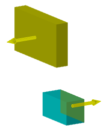
5. Constraint is applied, and "Mate constraint" objects are added to the "3D History" for each participating solid.
"Mate constraint". As part of the body.
The following context menu commands are available:
· Edit - causes constraint to be edited.
· End edit - completes the previously started editing.
· Rename (F2) - allows you to rename the constraint.
· Delete (Del) - delete constraint.
|
Important! |
To use this functionality, the 3D modeling engine C3D is required. |
Main menu: 3D - 3D Features -  Insert 3D Constraint.
Ribbon: 3D Tools - 3D Constraint - Insert 3D Constraint.
Toolbar: 3D - Insert 3D Constraint.
Command line: 3DINSERT.
The command allows you to impose a 3D constraint "Insert" on objects.
1. Call command "Insert 3D Constraint";
|
Important! |
When applying a constraint, at least one body must be unfixed. |
2. Select the edge of the first body (circle, arc);
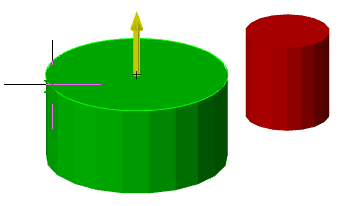
|
Important! |
A spline can be mistaken for a circle. Such a situation may arise, for example, when the edge of the hole is on a curved (cylindrical) plane. |
3. Select the edge of the second body (circle, arc);
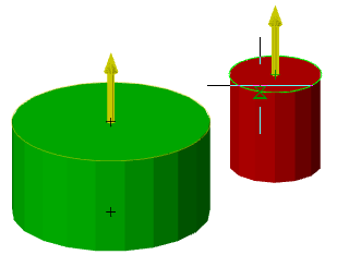
|
Important! |
A spline can be mistaken for a circle. Such a situation may arise, for example, when the edge of the hole is on a curved (cylindrical) plane. |
4. Enter the distance between the first or second geometry or select the "Co-Directional" context menu command;
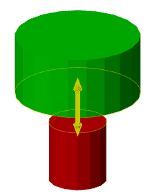
5. Constraint is applied, and "Insert constraint" objects are added to the "3D History" for each participating solid.
"Insert constraint". As part of the body.
The following context menu commands are available:
· Edit - causes constraint to be edited.
· End edit - completes the previously started editing.
· Rename (F2) - allows you to rename the constraint.
· Delete (Del) - delete constraint.
|
Important! |
To use this functionality, the 3D modeling engine C3D is required. |
Main menu: 3D - 3D Features -  Angle 3D Constraint.
Ribbon: 3D Tools - 3D Constraint - Angle 3D Constraint.
Toolbar: 3D - Angle 3D Constraint.
Command line: 3DANGLE.
The command allows you to impose a 3D constraint "Angle" on objects.
1. Call command "Angle 3D Constraint";
|
Important! |
When applying a constraint, at least one body must be unfixed. |
2. Select the geometry of the first body (plane or edge);
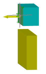
3. Select the geometry of the second body (plane or edge);
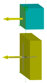
4. Select "Axis of rotation" if necessary. When specifying an angle between two primitives, the default angle scheme is used in the range 0-180. In order to cover the entire range of angles, an axis of rotation is needed. Also, setting the axis allows you to more correctly determine the direction of rotation. The axis must be perpendicular to both directions;
5. Enter the angle in degrees between the first or second geometry;
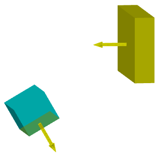
6. Constraint is applied, and "Angle constraint" objects are added to the "3D History" for each participating solid.
"Angle constraint". As part of the body.
The following context menu commands are available:
· Edit - causes constraint to be edited.
· End edit - completes the previously started editing.
· Rename (F2) - allows you to rename the constraint.
· Delete (Del) - delete constraint.
|
Important! |
This functionality requires a C3D 3D modeling engine. |
Main menu: 3D - 3D Features -  Tangent 3D Constraint.
Ribbon: 3D Tools - 3D Constraint - Tangent 3D Constraint.
Toolbar: 3D - Tangent 3D Constraint.
Command line: 3DTANGENT.
The command allows you to impose a 3D constraint "Tangent" on objects.
The Tangent 3D constraint allows you to create more complex surface tangencies than the Mate 3D constraint.
Constraint is superimposed on:
• cylinder to plane;
• cylinder to cylinder;
• cone to plane;
• sphere to cylinder;
• sphere to plane;
• circular edge to straight edge;
• circular edge to circular edge.
1. Call command "Tangent 3D Constraint";
|
Important! |
When applying a constraint, at least one body must be unfixed. |
2. Select the geometry of the first solid;
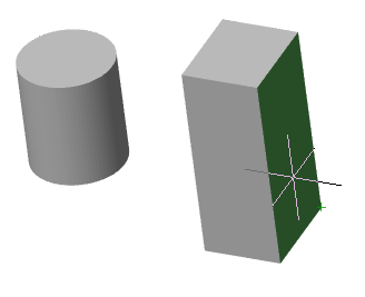
3. Select the geometry of the second body;
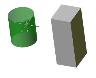
4. Constraint is applied, and "Tangent constraint" objects are added to the "3D History" for each participating solid.
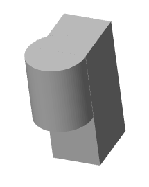
"Tangent constraint". As part of the body.
The following context menu commands are available:
· Edit - causes constraint to be edited.
· End edit - completes the previously started editing.
· Rename (F2) - allows you to rename the constraint.
· Delete (Del) - delete constraint.
|
Important! |
This functionality requires a C3D 3D modeling engine. |
Main menu: 3D - 3D Features -  Symmetry 3D Constraint.
Ribbon: 3D Tools - 3D Constraint - Symmetry 3D Constraint.
Toolbar: 3D - Symmetry 3D Constraint.
Command line: 3DSYMMETRY.
The command allows you to impose a 3D constraint "Symmetry" on objects.
The Symmetry 3D constraint allows you to align 3D solid elements symmetrically about a selected plane.
1. Prepare objects: two symmetry objects and a plane. A face of a solid can be used as a plane.
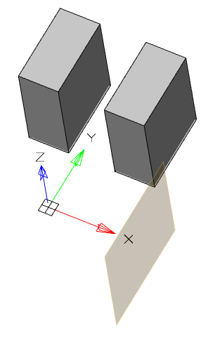
2. Call command "Symmetry 3D Constraint".
|
Important! |
When applying a constraint, at least one body must be unfixed. |
3. Select the plane of the first solid.
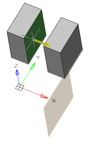
4. Select the plane of the second solid.
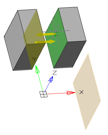
5. Select the plane relative to which the objects will be symmetrically positioned.
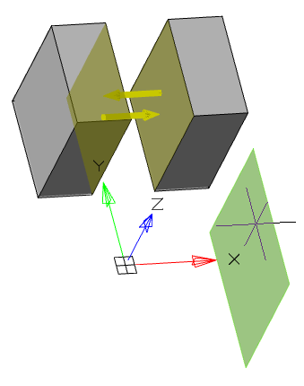
6. Constraint is applied, and "Symmetry constraint" objects are added to the "3D History" for each participating solid.
The distance from the first selected face to the plane will be the base for the second selected face.
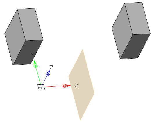
"Symmetry constraint". As part of the body.
The following context menu commands are available:
· Edit - causes constraint to be edited.
· End edit - completes the previously started editing.
· Rename (F2) - allows you to rename the constraint.
· Delete (Del) - delete constraint.
Main menu: 3D -  Convert to Mesh.
Ribbon: 3D Tools - Transform - Convert to Mesh.
Toolbar: 3D - Convert to Mesh.
Command line: MESHSMOOTH.
The tool allows you to convert "Parametric solid" (3D) and "3D Solid" in the object "Polyface Mesh".
1. Call command "Convert to Mesh";
2. Specify the objects that need to be converted;

3. Press the key "Enter (Space)";
4. Objects will be converted.
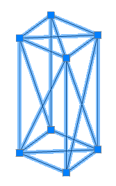
|
Note: |
If the objects were selected before the command "Convert to Mesh" is called, the conversion will be performed automatically immediately after the command is called. |
Main menu: 3D -  Convert to Solid.
Ribbon: 3D Tools - Transform - Convert to Solid.
Toolbar: 3D - Convert to Solid.
Command line: CONVTOSOLID.
The tool allows you to convert an object "Polyface Mesh" in the object "3D Solid".
1. Call command "Convert to Solid";
2. Specify the objects that need to be converted;
3. Press the key "Enter (Space)";
4. Objects will be converted.
|
Note: |
If the objects were selected before the command "Convert to sloid"is called, the conversion will be performed automatically immediately after the command is called. |
Toolbar for creating flat views and cuts from a 3D model.

By default, views are placed on the plane XoY.
|
Note: |
It is recommended to place views in the main coordinate system in order to avoid possible problems with the display of annotations. |
By default, global settings are used when inserting new views. Changes in global settings made after inserting a new view will be reflected in this view.
If you change any view parameter, this parameter will be unsettled from global settings and further changes of this parameter in global settings will not affect this view.
To remove the parameter override, use the command - Redefinition parameters.
Main menu: 3D - 2D Views -  Section.
Ribbon: 3D Tools - Section - Section Plane.
Toolbar: 2D Views - Section.
Command line: VIEWSECTION.
The team is designed to get a flat section of the body.
1. Call command "Section Plane".
2. Select the cutting plane:
· The secant plane can be any plane (working, plane GCS),as well as a flat surface of the solid.
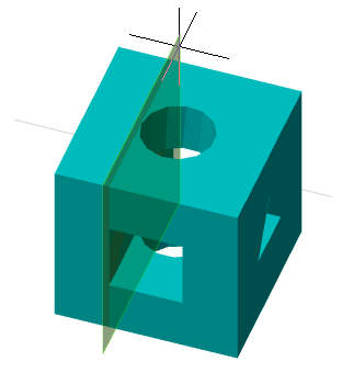
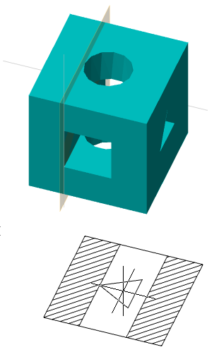
· A plane section can also be obtained by dissecting the solid not by a plane, but by a line. To do this, you must specify two points that will indicate the direction of the plane. If the cutting plane is indicated by a line, the plane will always be perpendicular to the XY plane.
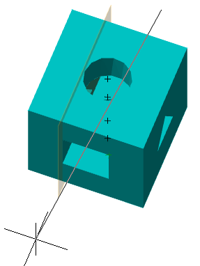
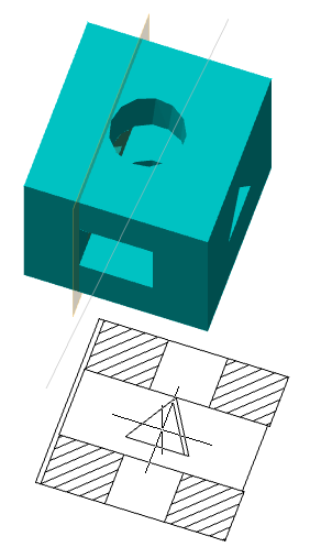
· A flat section can be obtained by indicating three points. To do this, select the command "3Points" from the context menu and select 3 points.
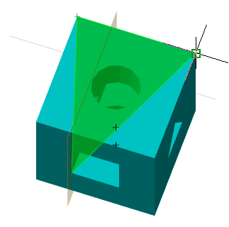
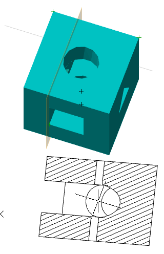
3. Specify the sheet where the view will be located. The command will offer a choice of all the sheets and model space that are in the document.
4. Select the position of the main planar section view. The view on the sheet is scaled so that it enters the sheet space and still has room for auxiliary projections.
5. Insert projected section views. Press the "Enter" key to finish inserting projection views. Auxiliary projections are inserted on the same sheet where the main view is inserted.
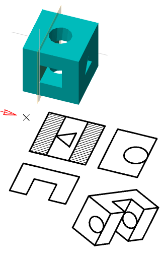
6. Will be built "NcDbSection" and "DriwingViewBlock". The corresponding objects will be added to the "3D History".
The following object "NcDbSection" properties are available in the properties panel:
· Is Live - controls the display of a section on a three-dimensional model. Parts, through which the cutting plane passes, will receive an incision.
|
Note: |
The cut on the 3D model is for viewing only. On such planes it is impossible to build sketches and the rest of the geometry. |
|
No |
Yes |
|
|
|
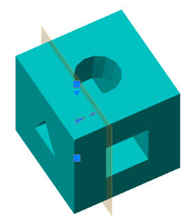
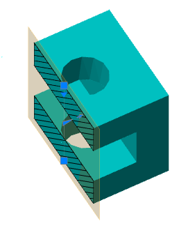
· Name - Name section. It is recommended to change the name in "3D History".
· Type - type section:
Plane - section on 1 plane
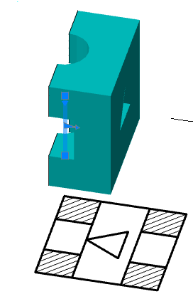
Boundary - section along 4 planes
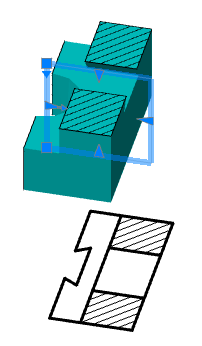
Volume - section along 6 planes
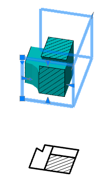
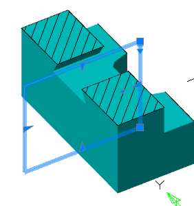
- grips change the position of the section in space. The upper grip is responsible for the movement, the lower grip is for the slope;
 - grips changes the position of the cutting plane (grip allows you to change the position of the plane only in one axis), the number of grips corresponds to the number of secant planes;
 - grip shear direction changes;
 - grip change of secant plane properties: Section Plane, Section Boundary, Section Volume.
Section. In "3D History" section is located in the root folder "Sections" and has child objects "View".
The following shortcut menu commands are available:
· Rename (F2) - rename a section.
· Delete (Del) - deletes the section and child objects from the model tree and model space.
· Hide - hides the section and child objects from the model space. Section icon becomes inactive.
· Show - shows the section and child objects in the model space. Section icon becomes active.
· ShowInDocument - focuses and highlights the section at the center of the model space.
· Rebuild - rebuilds an object in model space.
Main menu: 3D - 2D Views -  Projected view.
Ribbon: 3D Tools - Section - 2D View.
Toolbar: 2D Views - Projected view.
Command line: DRAWINGVIEW.
The command allows you to create two-dimensional views from the three-dimensional part.
1. Call command "2D View".
2. Select the parts you want to create from. To complete the selection, press the "Enter" key.
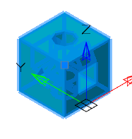
3. Specify the sheet where the view will be located. The command will offer a choice of all the sheets and model space that are in the document.
4. Position the main view on the plane. The view on the sheet is scaled so that it enters the sheet space and still has room for auxiliary projections.
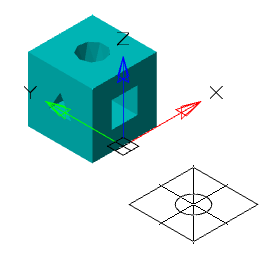
5. Position the necessary auxiliary projection views: flat and isometric. To finish inserting views, press the "Enter" key. Auxiliary projections are inserted on the same sheet where the main view is inserted.
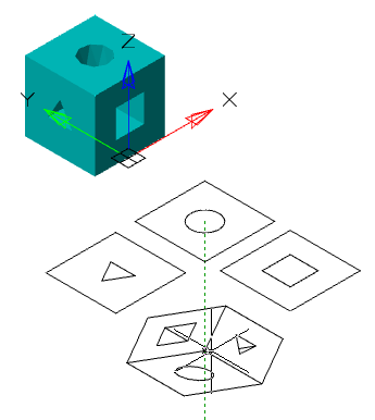
6. Will be created "Projected Views" and added to "3D History".
The 2D View is called for editing: by the "Edit" command of the context menu on the view, by the "Edit" command from the history of 3D constructions, by double-clicking the LMB.
Editing is allowed if the view does not depend on the section object.
If the view is in paper space, it switches to model space.
In edit mode, all currently projected objects are selected, you can add objects by selecting a new object, or remove them by deselecting an object.
To complete editing, you must press the "Enter" key, all related views will be rebuilt according to a new set of objects.
The following object properties are available in the properties panel:
Name - Name of the view. The name of the view is recommended to be changed in the "3D History".
Fill Angle - Angle of rotation.
Enable Update - The parameter controls the automatic view update when the part geometry is changed.
Alignment - The parameter controls alignment by coordinates with the set step when moving the view.
Show Hidden Lines - The parameter controls the display of hidden lines.
Show hatch - The parameter controls the display of hatching.
Moving grip - serves to move the view in model space.
View. In the "3D History" View belongs to part or section.
The following shortcut menu commands are available:
· Rename (F2) - allows you to rename a view.
· Delete (Del) - removes the view from the tree and model space.
· Hide - hides the view from the model space. View icon becomes inactive.
· Show - shows the view in the model space. View icon becomes active.
· Show hidden lines - shows hidden lines.
· Hide hidden lines - hide hidden lines.
· ShowInDocument - focuses and highlights the view in the center of the model space.
· Rebuild - rebuilds an object in model space.
Main menu: 3D - 2D Views -  2D Projected View.
Ribbon: 3D Tools - Section - 2D Projection.
Toolbar: 2D Views - 2D Projected View.
Command line: PROJECTIONVIEW.
The command creates a projection for the created views.
1. Call command "2D Projection".
2. Select the previously created view.
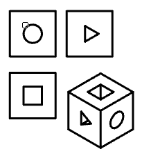
3. Position the projections on the plane. To complete the insertion, press the "Enter" key. Projection views vary depending on the location relative to the selected species.
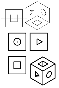
4. Will be created new objects Projected View" and added to "3D History".
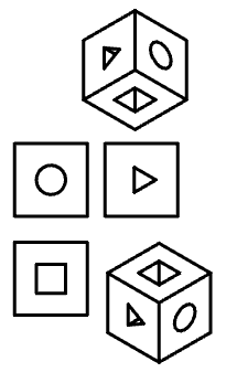
Main menu: 3D - 2D Views -  2D Section View.
Ribbon: 3D Tools - Section - 2D Section.
Toolbar: 2D Views - 2D Section View.
Command line: SECTIONVIEW.
The command creates a 2D section view of the created projected views.
1. Select Projected View. The command will draw sections in the same place as the main view. The scale is taken from the main view.
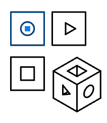
2. Call command "2D Section".
3. Specify the first and second cut points.
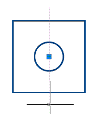
4. Place the view on the plane. Depending on the location (left or right of the line), the direction of the view will change.
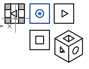
5. Will be created new object "Projected View" and added to "3D History".
Main menu: 3D - 2D Views -  Hatching Sections.
Ribbon: 3D Tools - 2D Views - Hatching Sections.
Toolbar: 2D Views - Hatching Sections.
Command line: DRAWINGVIEWAUTOHATCH.
The command analyzes all cuts in the drawing and corrects them so that each of the parts in all cuts has the same pitch and angle of dashed lines, which is different from other parts.
1. Previously, a section with a 2D view must be created, containing several parts.
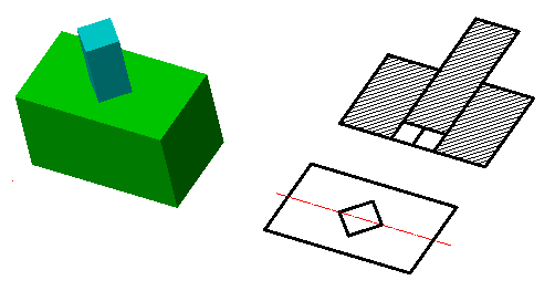
2. Call command "Hatching Sections". The team will analyze and correct the hatches. After the adjustment, the command will automatically end.
|
Before |
|
|
|
After |
|
|