
 De
De 

-
-
-
-
-
-
-
-
-
-
-
-
-
-
Polar Tracking Mode
-
-
-
-
-
-
-
-
-
-
-
-
-
-
-
-
-
-
-
-
-
-
-
-
-
-
-
-
-
-
-
-
-
Polar Tracking Mode
 Menu: Tools –
  Drafting settings… > Polar tracking tab
 Status bar: the
  button
Context menu of the button: On/Off
 Hotkeys: F10
Command line: DDRMODES, DSETTINGS, SE
Polar tracking mode helps to specify a point, set at a specified distance and angle from the last selected point. The dotted tracking line with a tooltip shows the distance from the last specified point and current angle value.
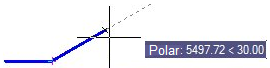
Using polar tracking mode, you can create geometric creations with any specified interval. For example, if an angle of 30 was selected, tracking lines will be displayed when the direction from this point to the cursor’s pick box is a multiple 30° (e.g. 60°, 90°, 120° and so on).
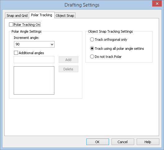
Specify the increment of the polar angle in the Polar tracking tab of the Drafting Setting dialog box or from the context menu of the POLAR button.
Parameters:
|
Polar tracking on (F10) |
Switches polar tracking mode on/off. |
Polar Angle Settings
|
Increment angle: |
Sets the angle step (increment) used to generate polar tracking lines (POLARANG system variable). For example, if an angle step of 30° is selected, then tracking lines will be displayed at 30°, 60°, 90°, 120°, and so on. The drop-down list shows commonly used angles: 90°, 45°, 30°, 22.5°, 18°, 15°, 10°, 5°. The step can also be set by anyone using the keyboard. The entered custom angle step when closing the dialog is automatically set to current. When you set the current step from the list, the custom angle is automatically deleted. |
|
Additional angles |
Enables/Disables the use of additional angles that do not obey pitch rules (system variable POLARMODE = 4). Additional angles are specified as an absolute value, not as an increment (system variable POLARADDANG). Using the Add and Delete buttons you can edit the number of additional corners (maximum 10) |
Object Snap Tracking Settings
|
Track orthogonal only |
In OSNAP mode tracking lines are only drawn horizontally and vertically. |
|
Track using all polar angle settings |
Switches on the mode for applying the parameters of polar tracking to object tracking. In this mode the cursor is moved from the point of object snap using aligning angles. |
|
Do not track Polar |
Switches off the polar angles tracking mode. |
Object snap modes
|
Track to alignment point |
Enables/Disables the mode of displaying tracking lines to feature points of the object. |
|
Clear track points on Shift+mouse wheel |
Enables/Disables the mode of erasing the snap point marker on the tracking line using the SHIFT key and the mouse wheel. When the mode is enabled, markers can only be erased using the “shift + mouse wheel” combination. When the mode is disabled, the markers are also erased when zooming/panning. |
Object tracking control is discussed in the Object tracking mode section.
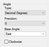
Format, accuracy, base angle and reference direction for angles are set in the Drawing Units dialog box:
To set the angles of polar snap lines:
On the Snap tab of the Drafting Settings dialog, enable the polar snap mode by checking the Polar Snap On box (F10).
In the Increment Angle field: select a standard value from the drop-down list or enter a custom increment value from the keyboard. When entering multiple angles, the last one entered is saved.
If you need to specify additional angles of the polar snap lines, check the Additional angles box. Enter the angle value in the field. Click the Add button. Enter up to 10 values. To delete an additional corner, select the corner in the section window and click the Delete button.
Click ОК.
You can also set the angles of polar snap lines and view the current increment angles in the context menu of the button:
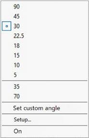
Options of the POLAR button context menu:
|
90, 45, 30, 22.5, 18, 15, 10, 5 |
List of standard, commonly used polar snap angles. The current increment of the polar snap mode has the |
|
35, 70 (Sample values) |
List of values of additional angles (if available). |
|
Set custom angle |
Sets a new angle increment using the command line. Command prompt: Enter angle: – enter the angle step (POLARANG system variable). |
|
Setup… |
Opens the Drafting Settings dialog on the Snap tab. |
|
On/Off |
Enables/Disables polar snap mode (AUTOSNAP system variable). |
 icon.
icon.
To create a point at a specified distance and at a specified angle:
On the Snap and Grid tab of the Drafting Settings dialog, enable the Snap mode by checking the Snap On box (F9). Set snap type – Polar snap. Enter the polar spacing.
On the Polar Tracking tab of the Drafting Settings dialog, enable the polar tracking mode by checking the Polar Tracking On box (F10). Set Angle Increment: and Additional Angles. Click ОК.
Set the first construction point. Specify a point located at a soecified distance and at a specified angle.