
 De
De 

MechWizard
 Main menu: Construction - Library objects - MechWizard -
  ScriptMaster.
Ribbon: Construction - MechWizard - ScriptMaster.
Toolbar: MechWizard - ScriptMaster.
 Library: Context menu command "Open with ScriptMaster" on any element library.
 Command line: SPSMASTER.
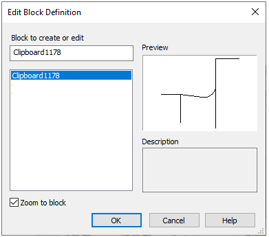
The command opens "ScriptMaster" for creating and editing a database object.
The title of the current element is indicated in the headers of the "ScriptMaster" dialog. An "*" signifies that unsaved changes were made to the item.

1. Main menu. Contains all commands for creating and editing objects and scripts. Contains sections:
· Object
· Edit
· Script
· Master
2. Toolbar. Contains basic commands for creating and editing objects.
·  "New object". The command opens a dialog for creating a new base element.
·  "Open". The command is designed to select another element from the base.
·  "Save". The command saves changes to the current object.
·  "Undo". The command cancels the previous action.
·  "Redo". The command redo the last undone action.
3. Object tree. In the object tree, you can navigate through the object properties and manage them through the context menu.
4. Workspace. The script and table, as well as other properties of the object are edited in the work area.
5. Notification area. The results of the script check and search / replacement are displayed in the notification area.
6. Status bar. The status bar displays the current state of work with the object:
· Setting the path to the current database;
· Current cursor position;
· Edit state - insert or replace;
· Script sign for reading or editing.
Menu item object allows it to work with database objects in nanoCAD Construction 23:
Object - creates a new element base (By pressing keys Ctrl+N or clicking on the icon  Create on the toolbar).
After issuing this command, a dialog box appears to New object

To create a new object, you must specify:
Folder in which to save the new object
Name (will be displayed in the browser)
Comment (will be displayed in the tooltip)
Select a way to create a new object

Create an empty object - creates a table and designs without having one script selected from the template.
Default template - empty script.
Create as copy of prototype - creates an object by copying the entire prototype object (along with the script, tables, performances and three-dimensional models.

Use the button  to select an object to create a prototype object.
Open - Open an existing part (keyboard shortcut Ctrl+O or icon Open on the toolbar).
After selecting the command, a dialog box appears Select the details allowing you to select or find the item in the current database in Construction Site 4.

Save - save changes to the current member base (keyboard shortcut Ctrl+S or icon  Save on the toolbar).
Set object preview - allows you to set as a preview for the object in the browser database objects nanoCAD.
Exit - close Master objects
In paragraph object available list of recently used items.
Menu item Edit allows you to work with the current database nanoCAD Construction 23:

Undo - cancel the last action (promptness pressing keys Ctrl+Z or clicking on the icon  Undo on the toolbar).
Redo - undo the last action (promptness pressing keys Ctrl+Y or clicking on the icon  Repeat on the toolbar).
Find - search for a given string on the script of the current element (promptness keys Ctrl+F).
Calling this command opens a dialog box Find

Looking provided an opportunity to take into account only whole words and case search string using by appropriate switches.
Also have the opportunity to select the search direction.
Go to the next matched string by pressing find Next.
After you click Cancel , you return to the previous menu.
Speas dropdown input field allows you to select the last used values.
Replace - search for a given string with a new one.
After calling this command, a dialog box appears Replace

When replacing provides an opportunity to consider only whole words and case search string using by appropriate switches. It is also possible to carry out replacement in the selected area or throughout the text.
Daylight without replacing the matched string to the next by pressing find Next.
When you click Replace matched string is replaced by a new one at the current position.
After you click Replace All all found strings will be replaced.
Button to return to the previous menu, press Cancel.
Go to - command allows you to go to a specific line (promptness keys Ctrl+G).

Find and replace on the database - allows you to search and replace strings in the base.

There are opportunities to search the entire database or in a folder, the search is case sensitive, whole words, as well as multi-line test, the search for the script, table, table name resources and facilities (Use advanced options )
Menu script allows you to work with the current script object database nanoCAD Construction 23:

Get script from other object - command allows you to copy the script from another object.
Set script to all objects in selected folder - script command sets the current object to all objects in the selected folder database elements nanoCAD Construction 23.
Show script of other object - you can view the script of another object without changing it.
Insert script template - command allows you to take in the script as the current object previously saved template.
Save script as template - allows you to save the current script object as a template for future use.
Show localized script - command allows you to view localized script based on the data of the resource table.
In general, writing the script for the majority of standard parts is not required. Just open the script details, like on purpose, and copy it. However, it must be remembered that the parameters in the model (figure) must strictly match the prototype.
nanoCAD Construction 23 is a convenient mechanism for self-compilation step algorithms that control the behavior of the items in the time of insertion and editing object - Master browser.
Call Master browser via the menu item Master / Script wizard
At any step of the script wizard may move buttons << Back and Next >> .
Button Cancel exits the wizard.

Object description (Property Description). This parameter is optional, it describes the common name of the object. For example, nut, bolt, etc.
Object type (type). This parameter is required, it is advisable to fill it in Latin characters. Serves to identify the object as belonging to a group. For example, StdArborParts - standard parts shaft, StdJointParts - fastenings.
Object Name (Name of facility). This parameter is required, it is advisable to fill it in Latin characters. Defines elements within the group, given strTheType. For example, a screw bolt - Screw, for nuts - Nut, for washers - Washer etc.
Object subtype (subtype). Additional parameter, it is desirable to fill it in Latin characters. Defines a specific subtype of GOST. For example, if the name of the object - Nut (Nut), then simple nuts subtype is Simple, from crown - Castle etc.
These parameters set by the user, based on its project object interaction, and can be arbitrary. Hard list is not, and they can be changed at any time. They will only be used in scripts to automatically establish dependencies (details - in the description of scripts).
Specification. Description line items for transmission specification.
Not used
All parameters specified in the table, are automatically available for operations over them from the program during the insert or edit the object. If a variable is used only in the process of creating a graphic image, then use it in the script is not necessary.
Protected (used internally)
If necessary, display the parameter dialog during insertion.
Public (visible)
Used to transfer parameters during insertion and editing of other objects.
Changeable (available for editing)
Available to change other objects in the editing process. Variable of the property, will pick up from the table and the necessary parameters on the basis of the obtained values to reconstruct the details of the model.
Set parameter in the dialogue
Variable for which this flag is set to be available for editing of dialogue insert details.
Dynamic selection
Processed when the position of the cursor relative to the insertion point of the object according to the formulas in the designated parameter value in the range of "minimum value" - "Maximum".
Calculate after dialouge is shown using dynamic selection by expression
Calculated after the call dialogue and visual selection as expression in the Parameter Value.
Dont calculate parameter
Defines the minimum value. Can be expressed as a function of other parameters. Determination of the value of the parameter as a function of the cursor or other parameters. Available functions may be called from the context menu or manually entered into the appropriate input box.
Minimum value
Defines the minimum value. Can be expressed as a function of other parameters.

Context menu is available in the input field.
Maximum
Defines the maximum value. Can be expressed as a function of other parameters. Context menu is available in the input field.
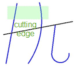
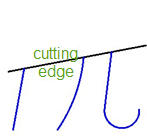
Add a line in the drawing model, rendering which we will operate from the dialog during the insertion of parts (for example, they will be highlighted Magenta). Pressing the button  will open a dialog box object properties and assign as a condition of their appearance in the drawing text parameter. In this case SLICE.

Size "S", necessary for proper recognition, automatically appears in the parameter list, but you must enter a parameter draw.

Fragment dialog box Properties settings

In the name field switch is set "Cut". The parameter rendering paste from the context menu variable "SLICE".
After the completion of the script retain the item and exit the editor. Of the database tree select our item and insert it into the model. In the editing dialog parts we have a switch incision through which we can control the rendering of relevant lines.

Workplanes determine the position of the items in the time of insertion and editing. Determination of working planes dialog box to the work plane.


 Creating a plane parallel to the plane OYZ

 Creating a plane parallel to the plane OXZ

 Creating a plane parallel to the plane OXY
In this step, you must identify the available options in the menu items. The selection is made by setting a checkmark APPLICABLE parameter
In this step, display conditions defined species . The selection is made by setting a checkmark APPLICABLE parameter and determining the conditions of his hiding
In this step, there are the following settings:
· Show dialogue before object is inserted
· Show object while inserting
· Regenerate object suppression contour after inserting

In this step, you can view and edit the resulting script. Clicking on the button Save and OK to apply the current script items

This is the final step.
Creating dependencies for interaction with other items going online.
Call Master dependencies via menu Master / Master Dependency .
Further, following the screen prompts on the command line, place the drawing model details and select the items with which it must interact.
After placing the parts in the drawing, a dialog box Managing Dependencies. Functionally, the dialog box is divided into two parts bookmarks. Bookmark this Parametric dependence and Assembly constraints.

Definition of parametric relationships occurs directly in the dialog box. It's enough to double-click on the option to specify the details of the child (it will automatically appear in the left-hand side) and bring it into line with the parameter of the parent object. In the right-hand side can be used mathematical expressions.
Types of assembly and parametric relationships are defined in the dialog box. Parameters can serve as table settings objects and definable expression.
 Axial and surface alignment
 Surface alignment
 Axial alignment
 Direction
 Sets the direction for the dependencies (Counter directional / Co-directional)
Once all the dependencies are installed, you can click OK, successively pass through the dialog boxes and set the options you want.
Eventually, an automatically generated string specifications necessary to automatically detect dependencies.
Master of string of specification
Formation data for transmission to the specification can be done in automatic and semi-automatic modes. Some information can be inserted on the basis of the table of parameters associated with the geometry of the figure, the part can be entered manually in the editing dialog standard parts.
Call Master BOM line via menu Master / Master BOM line .
In the drop-down list are tabulated parameters involved in drawing details.

For a complete description of information on standard parts must be able to adjust or supplement information. For example, cover screws or the class thread. In this case, just add a "#".
The editor position will be able to insert text between the two lattices, and then save.


Tree object contains the following sections:
· Description ;
· Parameters;
· Methods;
· Forms;
· Script .
If the open file has been modified, its wood properties can be irrelevant. To actualize the properties tree to choose the context menu to update the object tree.
When you click on the section Description of the workspace displays the following properties.

Property name - the name of the object to be displayed in the browser database.
Comment is displayed in the tooltip to the object.
Standard product allows you to set the standard (GOST, DIN, ISO, etc.).
Part list entry, is usually not be filled in the properties, and the variable defined in a script.
You can also put a tick:
Object have 3D view.
Cutting in detail
Object for 3D only.
In addition, the properties of the unique identifier for the object.
Section Parameters contains three subsections:
· public,
· protected,
· tabular.

The public section Upcoming shows a table of open (public) parameters along with their comments.

Furthermore, the parameters are displayed in a tree branch.
Section Protected contains a list of protected (protected) parameters, which are also displayed in a table and drop-down list of branches in the tree object.
Section Table includes a list of tables detail
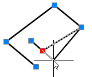
Table and column of the table in the current workspace synchronized depending on the position of the cursor in the object tree. Tables in the object may be a few, while the identification is made on behalf of the table. Popup menu when the cursor position on the table includes the following tools:
When you select table name as a prefix to the parameters of an appeal to the names of variables are prefixed with the table name. For example,Table0.dr.
You can add / delete rows from a table and add a parameter to a table.
There is also exported to Excel, text format and import from them.
Whenever the context menu on a separate parameter tables are available options remove a single parameter and set the type (Valid (Real), String (String) or a (Integer).
To rename a table parameter, select it and click on his name left mouse button, or press F2. If the parameter name has changed, it will automatically run search and replace in the script to a new name parameter correctly processed by the script.
Section Methods includes event handlers and custom functions.
When selecting a specific function in the script is its description (synchronized current line).
Red light  icon in the function indicates the presence of a function in the script is present,
 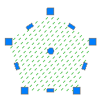 white - about lack. When you double clicking on the corresponding function in the script created by its pattern.
Section Versions list includes 2D and 3D versions
When selecting the root partition versions are all the performance, and the choice of a particular (for example, Version 1) - displays the filtered views of this execution. To create a two-dimensional view of a new version should be specified in the context menu Add performance - automatically create 2D views.
To create this kind of performance you need to select the required performance and the shortcut menu - Add 2D view.
· 2D view - parametric graphic nanoCAD
· 3D view of the Construction Site 23 - script to create a solid model (opening section of the shaft, etc.)
Deleted when you delete all kinds of performance of this version.
To set the parameters of the form, select it, and the right side of the workspace to set view orientation (Front, Left, Top , etc.) and the type of form ( cut, cut C, C size etc.).
In the context menu, you can select types of operations on this performance.
These options add \ remove kinds of current version:
The following context menu options are designed to work with the selected view of the current execution.
Recognize view - parametric recognition graphics nanoCAD.
Nonparametric recognize view - simple nonparametric reference charts, graphics taken from the object as it is.
Edit view as text - description of species opens in a text editor.
Set preview from objects - objects selection nanoCAD to create a preview of this species.
Import preview picture from file - creating thumbs on the basis of the previously saved file.
Export preview picture to file - Saves the preview in a file.
Database objects nanoCAD Construction 23 supports the use of custom dialogs for inserting and editing. Creating such dialogues (forms) is made in Form Editor, which can be accessed from the dialog boxes Create Group, Create marker and Object Wizard .
Button  Open the form editor.
Menu
File
· Test. Opens the form for viewing and testing.
· Output. Closes the form editor.
Correction
· Cancel. Cancels the previous execution of operations.
· Cut, copy, paste 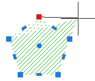

 . Command working with the clipboard.
· Select all. Selects all the controls on the panel shape.
· Remove. Deletes the selected controls from the form.
· Group. Group the selected controls.
· Ungroup. Cancels the grouping selected controls.
View
· By ... edge. Alignment commands selected controls along one edge.
· Align dimensions. Aligns the selected controls dimensions.
· Above and below. Reverses the order of the tab selected control by moving it up a level or down
· Forward, backward . Changes the tab order of the selected control by moving it to the first or the last level.
· Tab order 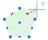 . Includes display serial numbers tab controls.
· To set the tab order to be pressed sequentially controls on the left mouse button. Tab order will be set according to the sequence control option.
· Properties. Enables and disables the additional window Properties.
· Variables. Enables and disables the additional window variables.
· Grid 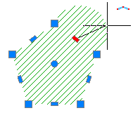 . Turns on and off the grid and snap to grid.
· Indents 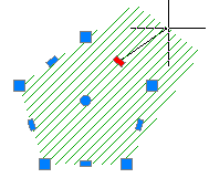 . Enables or disables the frame shape
Insert
There are commands insert controls
·  Switch.
·  List.
List.
·  Combo box from the database .
·  Text.
Text.
·  Group.
·  Figure.
·  Panel.
·  Button.

·  Table.
·  Viewing.
Forms panel
On the forms produced occupancy controls.
In the context menu of the forms are available editing commands: cut, copy, paste, group, ungroup.
To add a control to the form by one of the following ways:
· Select the desired control from the menu Insert or toolbar. Specify the insertion point and set the dimensions of the control panel on the form.
After adding the control you want to bind it to a field in the Properties.
· In the open window, Variables , select the variable for which you want to add a control. Left-click on the variable in the list, and holding down the mouse button, move the cursor to the panel shape. Release the mouse button. Panel forms added group controls - text and input field .
If you insert a control from the window variables hold down Control, then it is possible to select the type of control.
Selection of the control panel forms can be accomplished in several ways:
· Single click of the left mouse button. Selected one control.
· Single click of the left mouse button while pressing Control . If the control is not selected, it is added to the current set. If a control is selected, it is removed from the current set.
· Choosing a crossing . Click the left mouse button in the space bar form. Holding the button down and dragging a selection box set. Selected controls that are fully or partially captured by the selection frame.
Editing the size of the control is done by using the " grips ". When the grid is resized with a certain step.
Changing the position of the selected controls performed with the left mouse button on one of the selected items. When the grid movement occurs incrementally.
Align controls
In the menu View available commands align controls on edge and size.
Controls aligned to the left, and then by size .
Grouping controls
Working with multiple controls may need to be fixing their relative position. If grouping is fixed relative position of the controls, and when you move one of the other grouped elements also move.
Select panel forms controls and issue the Group. Selected controls will be grouped.
Removing Controls made the command Delete.
Test the form
Before completing the form creation is recommended to execute the test to view the form.
Variables window
In the Variables are parameters of the object ( marker , database object , group ).
Icon  marked parameters that are associated with controls editable form
Properties window
In the Properties lists the properties of the selected controls on the form. At the bottom there is a line prompt with a brief description of the selected property
Interaction of the form with the script
Interaction of the form with the script
The form and the design elements located on it interact with the script using properties and events.
Properties
All form properties start with a prefix "Form."
Control properties (design elements) start with a prefix "Form.$$$", where $$$ — name of the control on the properties panel of the form editor, case-sensitive.
Example:
Form.editbox.Value = "";
When accessing the control value (design element), the ".Value" parameter can be skipped.
Example:
Form.editbox = "";
For controls associated with script variables, the value can be passed through a variable.
Example:
// Bind the variable
Form.editbox.Field = "strType";
//...
OnDialogChanged {
// The next three lines do same.
// If values conflict,
// priority is taken into account.
// Priority decreases from top to bottom:
Form.editbox.Value = "";
Form.editbox = "";
strType = "";
}
While the form is active, you can work with its properties and the properties of its controls as with ordinary variables. In this case, the changes made in the script will be applied to the form after exiting the reactor function.
function OnDialogChanged
{
if (Mode == 1) {
Form.groupbox.Visible = FALSE;
Form.Lable1.Left = 50;
} else {
Form.groupbox.Visible = TRUE;
Form.Lable1.Left = 10;
}
Form.editbox.Left = Form.Label1.Left + 40;
Form.Label1.Right = Form.Label1.Right + 38;
}
|
Property |
Access |
Note |
|
Form.Count |
read |
The number of controls on the form. |
|
Form.Width |
read |
The width of the form's client area. |
|
Form.Height |
read |
The height of the form's client area. |
|
Form.Help |
full |
Link to the reference manual. If the path is relative, it is padded relative to the path to the project's Help folder. May be: - the path to the chm-file with or without the chapter (don't specify the protocol). - link to file - NormaCS page or document: http://help.spds.ru (Protocol is obligatory). - help index |
|
Form.$$$ |
full |
The value of the control. |
|
Form.$$$.Value |
full |
The value of the control. |
|
Form.$$$.Enabled |
full |
Control enabled/disabled. |
|
Form.$$$.Visible |
full |
Control visible/invisible. |
|
Form.$$$.Field |
full |
The name of the script variable associated with the control. |
|
Form.$$$.Tooltip |
full |
Hint text. |
|
Form.$$$.Left |
full |
Control size - indent on the left. If a binding was set in the form editor, after changing the dimensions, the coordinates of all controls will be recalculated taking into account these changes. |
|
Form.$$$.Top |
full |
Control size - indent from above. |
|
Form.$$$.Right |
full |
Control size - indent on the right. |
|
Form.$$$.Bottom |
full |
Control size - indent from below. |
|
Form.$$$.Count |
full |
The number of items in the list or dropdown list. |
|
Form.$$$.Items[#] |
full |
The #-th element of the list or dropdown list. |
Eventы
An event handler in this context is a script function that is called in response to an event on the form. Events will be called form properties that store the names of event handlers. There are events of the form itself and events of its controls. You can work with them as with normal form properties.
Example:
//Assign the OnChange event to the OnEditChange function
Form.editbox.OnChange = "OnEditChange";
|
Event |
When called |
|
Form.OnShow |
Before showing the form. All form properties are already defined. |
|
Form.OnClose |
Before closing the form. |
|
Form.$$$.OnChange |
After changing the value of the control by the user. Changing a control from a script does not generate this event. |
|
Form.$$$.OnEnter |
When the control receives input focus. |
|
Form.$$$.OnLeave |
When the control loses input focus. |
Switches
The logic of the switches is somewhat different from other design elements. Multiple radio buttons are bound to the same script variable. Each of them is set to some value. The variable is set to the value of the enabled switch. The value is of type string. If "-1" is set, the value is assigned automatically, starting from 1, in TAB order. In this case, the value type will be numeric.
Radio buttons associated with a single variable are considered a group. Only one radio button can be enabled in a group. If the variable is not assigned, radio buttons located inside the same control are grouped. This is usually a Group or Panel.
Examples
Event handling. In the script code, bind the Edit control to the script variable d. When the Edit value changes, update the text in the Static label.
· Solution 1. When the EditBox value changes from the form, the OnDialogChanged function will be called. Assign EditBox control Field name = d. The EditBox control will automatically synchronize its value with the d variable.
function OnDialogChanged
{
Form1.editbox1.Field = "d";
Form1.static1 = "Hole diameter: " + d + "mm";
}
· Solution 2. Assign an OnChange event handler to the EditBox control.
function OnDialogChanged
{
Form1.editbox1.OnChange = "OnEditChanged";
Form1.editbox1 = d;
}
function OnEditChanged
{
d = Form1.editbox1;
Form1.static1 = "Hole diameter: " + d + "mm";
}
· Solution 3. Let's combine both previous solutions. The d variable will be synchronized with the EditBox control automatically, and the text of the Static label will be updated from the OnChange event handler.
function OnDialogChanged
{
Form1.editbox1.OnChange = "OnEditChanged";
Form1.editbox1.Field = "d";
}
function OnEditChanged
{
Form.Label = "Hole diameter:" + d + "mm";
}
List management. Build a list of values in a combo dropdown list.
function OnDialogChanged
{
// You can set the number after the values, but before the values - somehow clearer.
Form.Combo.Count = 5;
// Elements are numbered from 1.
Form.Combo.Items[1] = “(нет)”;
Form.Combo.Items[2] = “Item1”;
Form.Combo.Items[3] = “Item2”;
Form.Combo.Items[4] = “Item3”;
Form.Combo.Items[5] = “Item4”;
// This command will fail because there are only 5 items in the list.
Form.Combo.Items[6] = “Item5”;
}
Form properties
|
General |
|
|
Help URL |
|
|
Caption |
|
|
Editor |
|
|
Top margin |
8 |
|
Height |
400 |
|
Left margin |
8 |
|
Bottom margin |
8 |
|
Margin |
|
|
Right margins |
8 |
|
Grid |
|
|
Grid step |
8 |
|
Width |
400 |
|
Note: |
In the "Help" parameter, the path to the user help is entered. User help will be invoked if the focus is on form control. If the focus is on the "Cancel" or "OK" buttons, the help of standard elements will open. |
 Input field. The input field is used to enter numeric or symbolic expressions for further processing.
Properties command:
|
View |
|
|
Visible |
|
|
Alignment |
On the edge |
|
Multiline |
|
|
Flat |
|
|
Tip |
|
|
Linking |
(None) |
|
Enable |
|
|
Text |
None |
|
Formatting |
|
|
Basic |
|
|
Name |
editbox1 |
|
Class |
After entering |
|
Variable |
|
|
Type |
Line |
|
Position |
|
|
Upper limit |
56 |
|
Height |
56 |
|
Left boundary |
176 |
|
Lower limit |
112 |
|
Right boundary |
232 |
|
Width |
56 |
|
Measurements |
|
|
Meter |
|
|
Mode |
Auto |
|
Regime change |
|
|
Developments |
|
|
Activation |
|
|
Deactivation |
|
|
To change |
|
 Checkbox. Allows you to monitor on/off.
Properties command:
|
View |
|
|
Visible |
|
|
Tip |
|
|
Linking |
(None) |
|
Allowed |
|
|
Text |
Flag |
|
Basic |
|
|
Enabled |
|
|
Name |
checkbox |
|
Class |
Flag |
|
Variable |
|
|
Position |
|
|
Upper limit |
8 |
|
Height |
16 |
|
Left boundary |
8 |
|
Lower limit |
24 |
|
Right boundary |
72 |
|
Width |
64 |
|
Developments |
|
|
by clicking |
|
Description:
Several switches are associated with the same variable script. Each of them set any value. Variable is set to the included switch. Value is of type string. If set to "-1" value is assigned automatically starting with 1, in the tab order for TAB. In this case, the value type is numeric. Switches associated with a single variable group are considered. In the group may be included in only one switch. If a variable is assigned, grouped switches located inside one of the control. Usually this group or panel.
Properties command:
|
View |
|
|
Visible |
|
|
Tip |
|
|
Linking |
(None) |
|
enabled |
|
|
Text |
Switch |
|
Basic |
|
|
Included |
|
|
Value |
-1 |
|
Name |
radiobutton |
|
Class |
Switch |
|
Variable |
|
|
Position |
|
|
Upper limit |
24 |
|
Height |
24 |
|
left boundary |
8 |
|
Lower limit |
48 |
|
Right boundary |
112 |
|
Width |
104 |
|
Developments |
|
|
by pressing |
|
Example of using.
Switches allow you to choose between discrete values, the result is displayed in the input field
List. Used to select one value from a specified list.
Properties command:
|
View |
|
|
Visible |
|
|
Tip |
|
|
Linking |
(None) |
|
Enable |
|
|
Text |
-1 |
|
Basic |
|
|
Data |
"Element 1" |
|
Name |
Listbox |
|
Class |
List |
|
Variable |
|
|
Current |
-1 |
|
Position |
|
|
Upper limit |
48 |
|
Height |
40 |
|
Left boundary |
8 |
|
Lower limit |
88 |
|
Right boundary |
104 |
|
Width |
96 |
|
Developments |
|
|
Activation |
|
|
Deactivation |
|
|
To change |
|
 List from the database.. Used to select one value from a pre-specified list in the database.
Properties command:
|
View |
|
|
Visible |
|
|
Tip |
|
|
Linking |
(None) |
|
Enable |
|
|
Text |
|
|
Basic |
|
|
Data |
|
|
Name |
Listbox1 |
|
Class |
List of base |
|
Variable |
|
|
Current |
|
|
Position |
|
|
Upper limit |
96 |
|
Height |
60 |
|
Left boundary |
8 |
|
Lower limit |
156 |
|
Right boundary |
104 |
|
Width |
96 |
|
Developments |
|
|
Activation |
|
|
Deactivation |
|
|
To change |
|
 Combo box. Designed to select from the specified list or enter an arbitrary value.
Properties command
|
View |
|
|
Visible |
|
|
Tip |
|
|
Linking |
(None) |
|
enabled |
|
|
Text |
Combo box |
|
Basic |
|
|
Data |
|
|
Name |
combobox |
|
Class |
combobox |
|
Variable |
|
|
Editable |
|
|
Position |
|
|
upper limit |
168 |
|
Height |
76 |
|
left boundary |
8 |
|
Lower limit |
244 |
|
Right boundary |
104 |
|
Width |
96 |
|
Developments |
|
|
activation |
|
|
deactivation |
|
|
to change |
|
Combo box from the database. Designed to select from the specified list or enter an arbitrary value.
Properties command:
|
View |
|
|
Visible |
|
|
Tip |
|
|
Linking |
(None) |
|
Enabled |
|
|
Text |
|
|
Basic |
|
|
Data |
|
|
Name |
combobox1 |
|
Class |
combobox |
|
Variable |
|
|
Editable |
|
|
Position |
|
|
Upper limit |
208 |
|
Height |
64 |
|
Left boundary |
8 |
|
Lower limit |
272 |
|
Right boundary |
104 |
|
Width |
96 |
|
Developments |
|
|
Activation |
|
|
Deactivation |
|
|
To change |
|
Properties command:
|
View |
|
|
Visible |
|
|
Headset |
(Info) |
|
Tip |
|
|
Linking |
(None) |
|
Transparent |
|
|
Text |
Text |
|
Background |
|
|
Basic |
|
|
Name |
static |
|
Class |
Text |
|
Label |
|
|
Variable |
|
|
Position |
|
|
Upper limit |
280 |
|
Height |
32 |
|
Left boundary |
8 |
|
Lower limit |
312 |
|
Right boundary |
104 |
|
Width |
96 |
Group. Decorative element, designed to visually group several controls on the form.
Properties command:
|
View |
|
|
Visible |
|
|
Tip |
|
|
Linking |
(None) |
|
Enabled |
|
|
Text |
|
|
Basic |
|
|
Name |
groupbox1 |
|
Class |
Group |
|
Variable |
|
|
Position |
|
|
Upper limit |
320 |
|
Height |
38 |
|
Left boundary |
8 |
|
Lower limit |
358 |
|
Right boundary |
104 |
|
Width |
96 |
|
Developments |
|
|
Activation |
|
|
Deactivation |
|
|
To change |
|
Figure. Insert a simple bitmap to the form.
Properties command.:
|
Basic |
|
|
Name |
Image |
|
Class |
Drawing |
|
Variable |
|
|
View |
|
|
Visible |
|
|
Data |
(Info) |
|
Tip |
|
|
Linking |
(None) |
|
Transparent |
|
|
Proportionally |
|
|
Stretch |
|
|
Position |
|
|
Upper limit |
360 |
|
Height |
57 |
|
Lleft boundary |
8 |
|
Lower limit |
417 |
|
Right boundary |
105 |
|
Width |
97 |
Panel. Designed for grouping and align multiple controls on the form.
Properties command:
|
Basic |
|
|
Name |
panel |
|
Class |
Panel |
|
View |
|
|
Linking |
(None) |
|
Position |
|
|
Upper limit |
16 |
|
Height |
49 |
|
Left boundary |
112 |
|
Lower limit |
65 |
|
Right boundary |
185 |
|
Width |
73 |
Button. Control "button." Response by pressing the left mouse button.
Properties command:
|
View |
|
|
Visible |
|
|
Tooltip |
|
|
Linking |
(None) |
|
Allowed |
|
|
Text |
Button |
|
Main |
|
|
Icon |
-1 |
|
Name |
button |
|
Class |
Button |
|
Variable |
|
|
Position |
|
|
Upper Bound |
72 |
|
Height |
32 |
|
Left bound |
112 |
|
Lower limit |
104 |
|
Right border |
184 |
|
Width |
72 |
|
Developments |
|
|
by clicking |
|
Properties command:
|
Basic |
|
|
Name |
Control |
|
Class |
Table with filtering |
|
Variable |
|
|
View |
|
|
Visible |
|
|
Tip |
|
|
Linking |
(None) |
|
Enable |
|
|
Position |
|
|
Upper limit |
112 |
|
Height |
32 |
|
Left boundary |
112 |
|
Lower limit |
144 |
|
Right boundary |
184 |
|
Width |
72 |
Table . Table variables with the ability to view and select a row.
Properties command:
|
Basic |
|
|
Name |
Control1 |
|
Class |
Table with filtering |
|
Variable |
|
|
View |
|
|
Visible |
|
|
Tip |
|
|
Linking |
(None) |
|
Enable |
|
|
Position |
|
|
Upper boundary |
152 |
|
Height |
40 |
|
Left boundary |
112 |
|
Lower limit |
192 |
|
Right boundary |
184 |
|
Width |
72 |
Properties command:
|
View |
|
|
Visible |
|
|
Tip |
|
|
Linking |
(None) |
|
Enable |
|
|
Basic |
|
|
Name |
Control2 |
|
Class |
Views and performance |
|
Execution |
|
|
Show performance |
|
|
Types |
|
|
|
|
|
|
|
|
|
|
|
|
|
|
|
|
|
|
|
|
Display Types |
|
|
Shows the type form |
|
|
Position |
|
|
Upper limit |
200 |
|
Height |
32 |
|
Left boundary |
112 |
|
Lower limit |
232 |
|
Right boundary |
184 |
|
Width |
72 |


Preview. Preview box of the selected object from the database.
Properties command:
|
View |
|
|
Visible |
|
|
Tip |
|
|
Linking |
(None) |
|
Enabled |
|
|
Text |
PreViewControl |
|
Basic |
|
|
Name |
control3 |
|
Class |
Review |
|
Position |
|
|
Upper limit |
240 |
|
Height |
40 |
|
Left boundary |
112 |
|
Lower limit |
280 |
|
Right boundary |
184 |
|
Width |
72 |
Serves for quick creation of lists and their subsequent use in form controls and custom sorting in tables.
Dialog
The dialog is divided into two parts: Collection name and Collection members.

Collection management tools
 Add new collection.
 Delete collection.
Collection members management tools
 Add new collection member.
 Delete collection member.
 Delete all collection members.
 Move collection member upper.
 Move collection member down.
 Paste from clipboard.
Create and assign a collection while editing a form
In order to create a collection you need to:
1. Click the "Data" option in the DB-Listbox or DB-combobox. A dialog box will appear.
2. In the list of collections, call the "Add new collection" command and enter a name for the collection.

3. Set the composition of the collection.


4. Select a collection and click "OK" in the Collection Editor dialog box.
5. he created collection will look like this:

Creating custom filtering on a table
In order to create a collection you need to:
1. Go to Edit Table Dialog "Main Menu - Rows - Custom Sort...".
2. In the list of collections, run the "Add new collection" command and enter a name for the collection.
3. Set the composition of the collection.
4. Click "OK" in the Collection Editor window.
Purpose of custom filtering in a table
1. In the "Row grouping and merging" dialog box add a "User Sort" rule.
2. Select a collection and click "OK".
3. The custom sort created will look like this:
|
Important! |
Collections are saved to the database, they can be used in other objects nanoCAD Construction 23. Forms and tables have separate stores. Collections created by editors or administrators are available to everyone and cannot be edited by the user (the collection editing buttons will be grayed out). User-created collections are only accessible to the user. |
Section Table of resources designed to create a multilingual resource strings details.

In the context menu section, there are options to add and delete rows.

Each resource can have a name (Label), by which it will be referenced from the script (by writing the @Resource Name ). The property is selected, the row that corresponds to the name of the resource (or its ID) and the column corresponding to the application language. Thus, we can ensure the correct operation of applications of different locations on the same database. Of course, the current local line must be completed, otherwise for non-Russian locale is selected resource corresponding to the English language.
When switching to the section script in the workspace displays the script object.

In the context menu of the script contains option parsing script.

While parsing the functions performed consistently script object and passed to the notification system error messages. By double-clicking on a line in the notification area on the transition line of the script that contains the error.

Main menu: Construction - Library objects - MechWizard - 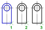 Add constraint.
Ribbon: Construction - MechWizard - Add constraint.
Toolbar: Add constraint ( "MechWizard").
Command line: SPCONSTRAINT.
In the dialog box Constraints:

In the dialog box set parametric and assembly (geometric) dependencies between database objects.
The window is divided into two parts:
Left - The child
Right - The parent object
Use  1-selected object and 2 were selected to the choice made in the drawing, respectively subsidiary and parent objects. After selecting an object in the corresponding half of the window, a list of parameters of the object, which includes:
· Property name
· List surfaces (work surfaces)
· The list object's parameters
· List of installed parametric relationships
· List of installed assembly constraints

On two tabs depending Parametric and Assembly constraints established relationship between parent and child objects.
Parametric dependence connects the parameters of objects.
Assembly dependence binds workplanes objects.
Button  New dependency. Allows you to create a new dependency
Button  Delete dependency. Deletes the selected list dependence
When adding or editing button is activated depending 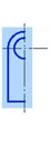 Save dependence, which allows you to save your changes.
Installing the parametric dependence
When installing the parametric constraints is associated parameters are recorded in the corresponding input fields located below the list object's parameters. Selecting the link parameters by double-clicking on the corresponding parameters in the list.
Installing assembly according
To install the switch assembly according to the tab Assembly constraints.
Choose binding surface by double-clicking on the appropriate working plane from the list.
Selecting the plane can also be done visually in the drawing by clicking labelled plane and the linked marker indicating the working plane of the object.
The choice of method depends overlay using the buttons at the bottom:
 Axial and surface alignment
 Surface alignment
 Combination axis
 Direction
Choose mutual orientation related planes using the buttons:
 Counter-directional
 Codirectional
Button  Bidirectional constraint. Enables two-way relationship in which a related parameter or surface of the parent object changes with appropriate changes to the child object.
Main menu: Construction - Library objects - MechWizard -  Connect objects.
Ribbon: Construction - MechWizard - Connect objects.
Toolbar: Connect objects ( "MechWizard").
Command line: SPCONNECTTO.
This command is used to overlay preset assembly and parametric dependencies on objects in the drawing.
After running the command must specify.
1. Child object - an object that will be joining.
2. Parent object - the object to which you will attach the child object.
Upon completion of the command will be imposed on the details of parametric and geometric constraints defined in their script..
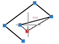
Main menu: Construction - Library objects - MechWizard -  Symmetry axis.
Ribbon: Construction - MechWizard - Symmetry axis.
Toolbar: Symmetry axis ( "MechWizard").
Command line: SPWIZSYM.
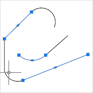
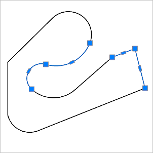
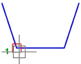
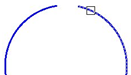
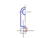
Select the segment to set it as the axis of symmetry. Drawing can contain multiple axes of symmetry. Symmetrical layout sketch relating to a particular axis is determined automatically by the recognition of a parametric model.
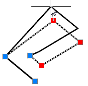
Main menu: Construction - Library objects - MechWizard -  Set Parameter.
Ribbon: Construction - MechWizard - Set Parameter.
Toolbar: Set Parameter ( "MechWizard").
Command line: SPWIZPARAM.
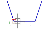
Button Set parameter is used for setting targets sketch. Press the button and select the object (sketch element). This will bring up a dialog box, the form of which depends on which object was selected.
When setting the size of the dialog box will look like:

Enter a parameter expression to control the size. The parameter can be set by a variable name or expression that is allowed to use the number and names of the variables related to mathematical and logical functions.
|
Important! |
Object parameter names should not coincide with the names of the teams nanoCAD (for example, can not be assigned to the parameter name HATCH or LINE) |
Expressions can be used the following functions:
· arithmetic operators +, -, *, /
· trigonometric functions sin(), cos(), tg() (the function argument is given in degrees)
· inverse trigonometric functions asin(), acos(), atg()
· taking the square root function sqrt()
· exponentiation function^ (recording format: x ^ y - x raising y)
· absolute value abs()
· rounded to an integer value int().
Logical operations:
· Min(x,y) - returns the minimum value of the argument;
· Max(x,y) - returns the greatest value.
· Iff (boolean, x, y) - returns the value of the argument x if the logical expression is true, or the value of y if the logical expression is false. Example of using the function, the result of which is similar to the function Min (x, y): Iff(x<y, x, y).
Valid logical conditions: >, <, == (equal), ! = (Not equal), > = (not less than), <= (not more).
Function within an expression can be nested.
When you set a graphic element sketch (segment, circle arc, circle, spline or shading) dialog box will look like:
Work items are supporting the construction of a thumbnail and are not displayed when you insert a model from the database. Performance object can be any graphic sketch element: line, arc of a circle, etc.
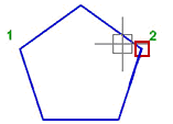
When setting the insertion point, a dialog box will look like:
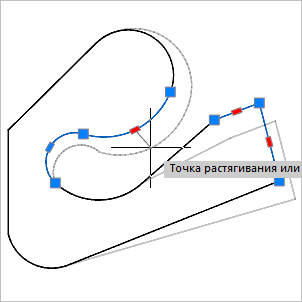
Distance along the axes OX and OY determines the position of the handle in the object. Distance can be set expression or numeric value.
Parameter on the x-axis and OX and OY is the name of the script variable whose value will change when stretching the handle.
Button 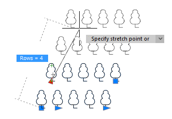 specify parameter lets take a parameter or drawing away.
In the sketch may include additional expressions for calculation of parameters. These expressions should be written a single line text entry format each line of text as follows:
X = EXPR
where X - the variable name;
EXPR - an expression that contains the names of variables, mathematical or logical functions.
Examples of additional rows of values:
· a = b*2 - assigning the result of an arithmetic operation;
· alpha = asin(b/c) - the use of trigonometric functions;
· k = iff(a>b, 1, 0) - assign a value to the condition;
· d = min(m1, 100) - the assignment of the smallest of the two values;
· g10 = sin(alpha*2) + sqrt(b^2 - c^3) / min(sin(a), cos(b)) - nested functions.
Sequence computing additional rows values - from left to right and top to bottom. Additional values values recognizing parametric form must be selected along with other sketch entities.
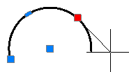
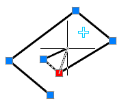
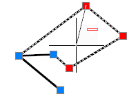
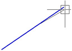
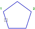
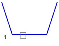
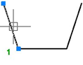
Main menu: Construction - Library objects - MechWizard -  Insert point.
Ribbon: Construction - MechWizard - Insert point.
Toolbar: Insert point ( "MechWizard").
Command line: SPWIZINS.
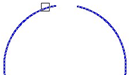
The insertion point should always be shown on the sketch of the parametric model. Click to choose its position on the sketch.
If you try to check the model or recognize the form of a sketch in which the insertion point is not specified on the command line, you are prompted to "Select insert point". Then you need to specify the sketch position of the insertion point.
In the case of several insertion points in the sketch, recognition will be considered only of the one that has been specified later, and all others will be ignored.
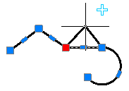
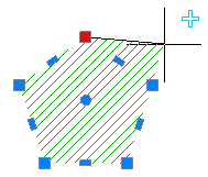
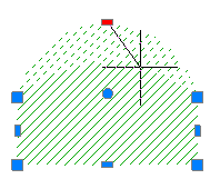
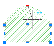
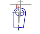
Main menu: Construction - Library objects - MechWizard -  Supression contour.
Ribbon: Construction - MechWizard - Supression contour.
Toolbar: Suppression contour.
Command line: SPWIZCONTOUR.
|
Important! |
The command prepares the sketch for recognizing the execution type of the base object. |
A suppression contour limits the area that the object overlaps with other graphics in the drawing. If the suppression contour is not specified, it is created automatically when the model is recognized by the external outlines of the part, and service objects are not taken into account.
1. Draw a closed polyline on the sketch that matches the shape and size of the required suppression contour (in the figure, a rectangle around the sketch).
2. Call the command "Supression contour".
3. Specify the constructed polyline. The contour is highlighted in green in the sketch.
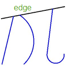
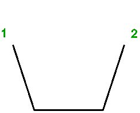
A prerequisite for the contour is the absence of self-intersections. To avoid self-intersections for a compound contour, create the contour manually, leaving a minimum "isthmus" between the areas:
|
Wrong |
Right |
|
|
|

If the suppression contour cannot be created automatically (the outer boundaries of the object do not form a closed contour), then when the object is inserted into the drawing, a corresponding warning message will be displayed. However, errors in the suppression contour do not affect the applicability of the recognized object, and can only appear in the wrong overlap of other objects in the drawing.
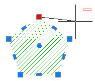
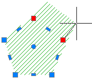
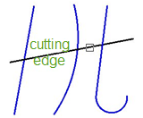
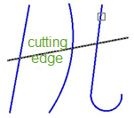
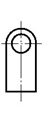
Main menu: Construction - Library objects - MechWizard -  Hatch contour.
Ribbon: Construction - MechWizard - Hatch contour.
Toolbar: MechWizard - Hatch contour.
Command line: SPWIZSECTCONTOUR.
|
Important! |
The command prepares the sketch for recognizing the execution type of the base object. |
A hatch contour defines the shaded area of an object in the drawing.
1. Draw a closed polyline in the sketch that matches the shape and size of the required hatch contour (in the figure, a rectangle around the sketch).
2. Call the command "Hatch contour".
3. Select the constructed polyline. The outline will be highlighted in red in the sketch.
A prerequisite for the contour is the absence of self-intersections. To avoid self-intersections on a compound contour, create the contour manually, leaving a minimum "isthmus" between the areas.
|
Wrong |
Right |
|
|
|
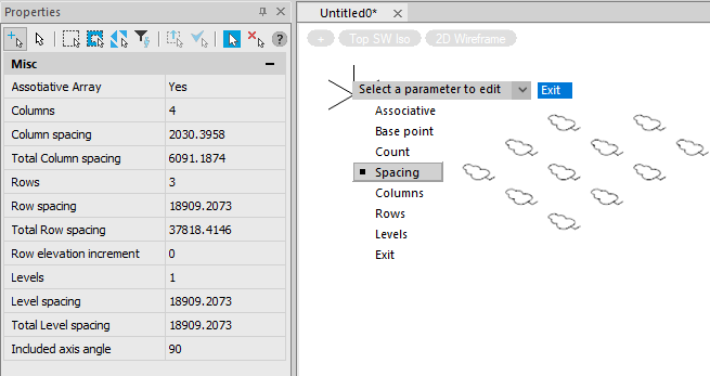
Main menu: Construction - Library objects - MechWizard -  Parametric model.
Ribbon: Construction - MechWizard - Parametric model.
Toolbar: Parametric model ( "MechWizard").
Command line: SPWIZARR.
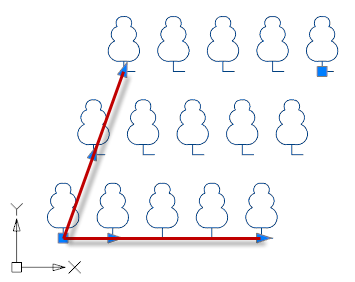
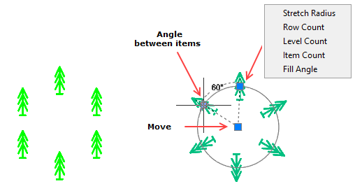
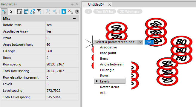
1. Create primitives of nanoCAD block and select the required dimensions in the sketch to determine its size and location.
2. Press the  array and selected block in the drawing.
3. In the dialog box, select an array type and parameters that control the construction of the array. Parameters can be assigned to both numeric and non-numeric values (variable names and expressions).

Every single unit with a unique name that is inserted into a sketch can be used only in a single array.
Main menu: Construction - Library objects - MechWizard -  Test model.
Ribbon: Construction - MechWizard - Test model.
Toolbar: Test model ( "MechWizard").
Command line: SPWIZ.
Checks sketch of a parametric model.
Highlight crossing window thumbnail and press Enter. If the sketch contains no errors, a message appears
If the sketch is not large enough, a message appears warning of an error.
The sketch is the original model of the parametric view of the object.

When creating parametric objects, the commands of the "MechWizard" toolbar are used.
1. Prepare a sketch. For correct recognition, all graphic elements of the sketch (including hatching) must be drawn with the appropriate linetype. Similar types (solid thick and thin, dash-dotted thin and thick) should be distinguished by the color set in the nanoCAD Construction settings.
2. Set the insertion point, optionally specify the axis of symmetry, sketch element options, suppression contour, hatch contour and paramentric array.
3. Dimension and assign variables and expressions to them.
4. Enter additional parameters as needed.
5. Check the sketch and make sure there are no errors.
Creating a template layout tiles
Example of creating a template layout tiles.
1. Create a sketch of the object. If the size of the tiles will not change, then the sketch is not required to specify the size.
Terms and method of creating a sketch of the parametric object described in section Rules for creating sketches .

2. Create an object and save it to the database. In a script, you must set the variable "type" (strTheType = "Plate")
3. Position the Bone in the drawing, insert the base of the two vectors and create a group. (see. Create user group ). These vectors determine the pace and direction of replication of the original group. The basic point of the vector must coincide with the insertion point of the object.

If only one vector will create one line layout in any mode selection area.