
 De
De  Es
Es  Fr
Fr 

-
-
-
-
-
-
-
-
-
-
-
-
-
-
-
-
-
-
-
-
-
-
-
-
-
-
-
-
-
-
-
-
-
-
-
Trace Tab
-
-
-
-
-
-
-
-
-
-
-
-
-
-
-
-
-
-
-
-
-
-
-
-
-
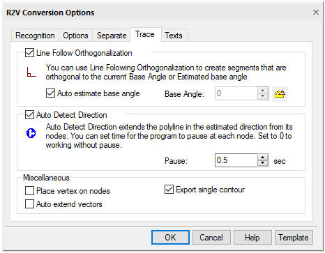
Trace Tab
To trace outlines, it is necessary to configure the parameters that affect the conversion procedure by this method.
In the R2V Conversion Options dialog box, open the Trace tab.
Trace tab
Trace tab options
|
Option |
Description |
|
Line Follow Orthogonalization |
When the box is checked, the polylines tracing automatically aligns the segments of the generated polylines perpendicular to each other. All segments are either perpendicular or parallel to the base direction. Base direction is set in the Base Angle field. When the Auto estimate base angle box is checked, the program automatically determines the base direction towards the longest polyline segment. The use of this option makes it easier to trace raster objects consisting of perpendicular segments (for example, tracing buildings on floor plans). |
|
Auto estimate base angle |
Automatically determines the base direction of orthogonalization of polyline segments. The base direction for each traced polyline is determined individually. |
|
Base Angle |
Enter the angle defining the base direction of the orthogonalization or click the button next to the field name and specify two points in the image - the value of the angle between the line connecting these points and the direction of the X axis will be shown in the Base Angle field. When you check the Auto estimate base angle box, the Base Angle field is disabled. |
|
Auto Detect Direction |
Enables a mechanism for determining the direction of continuation of tracing. Upon reaching the node point, the program tries to determine the next section of the raster line, which is a continuation of the traced object. |
|
Pause |
Specifies the time interval in seconds, during which the user should select a segment to continue tracing when working in the auto detect direction mode. If during the specified period the user does not manually specify another continuation, the program will continue tracing in the automatically selected direction. Setting this parameter to 0 specifies the trace procedure without delays. |
|
Place vertex on nodes |
When the box is checked, the program, while tracing polylines, inserts vertices at the intersections of the generated vector polyline with raster objects (at the node points) |
|
Auto extend vectors |
This checkbox sets the forced selection and trace of arcs and lines. When recognizing lines, you should specify two arbitrary points on the line and the program will automatically extend the line to its endpoints. When recognizing arcs, specify three arbitrary points on the arc, the program will automatically extend the arc to its endpoints. |
|
Export single contour |
When checked, tracing creates the outer contour of the object. If the checkbox is cleared, tracing creates both the outer contour of the object and the outlines for the inner closed regions (“holes”), if any. |