
 De
De  Es
Es  Fr
Fr 

-
-
-
-
-
-
-
-
-
-
-
-
-
-
-
-
-
-
-
-
-
-
-
-
-
-
-
Setting of the Show Boundary for a Raster Image
-
-
-
-
-
-
-
-
-
-
-
-
-
-
-
-
-
-
-
-
-
-
-
-
-
Setting of the Show Boundary for a Raster Image
 Ribbon: Insert –Reference – Clip >
  Image Clip
Menu: Modify – Clip >  New
New
 Command line: IMAGECLIP, ICL
The command allows you to insert a clip of the raster image into the drawing, to set the display on the screen and print only the required part of the raster image.
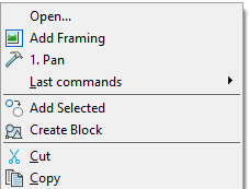
When a raster image is selected the command to show boundary becomes available from the context menu for your convenience:
Setting of the show boundary of the raster image affects its display in the current document, but does not change the source image.
Clipping of the raster image is done using a polygonal outline (rectangular, polygonal or closed polyline), whose vertices are inside the image boundary.
It is possible to specify a different clipping contour for each entry of the same raster image, but each entry can have only one contour.
The clipping contour can be turned off to display the original image and then back on to show the clipping image.
The clipping contours can be redefined. When you specify a new clipping contour, the old contour should be deleted.
After deleting the clipping contour, the raster image is displayed on the screen in its original boundaries.
The IMAGEFRAME system variable allows you to manage the visibility of the clipping contour and raster counter. If the system variable is set to value 1 (set by default), the counter is displayed on the screen and you can select it and print it. If system variable is set to value 0, the counter visibility is turned off and you cannot select it and print it. If system variable is set to value 2, the counter is displayed on the screen, but you cannot print it.
There are commands in the Modify menu – Object > Image > to make work with IMAGEFRAME system variable easier:
Frame On - Sets IMAGEFRAME = 1
Frame Off - Sets IMAGEFRAME = 0
Print Off - Sets IMAGEFRAME = 2
Options:
|
? |
Calls additional options to select the objects. |
|
|
Select_polyline |
Sets the limits contour using the selected closed polyline. The polyline should be created previously and consist of straight-line segments. |
|
|
Polygonal |
Sets the polygonal contour of the show boundary by sequenced specifying of the polygonal vertices. When you set the second and next vertices, you can see the following prompt in the command line: Next point or [Undo]: Option: |
|
|
Undo |
Sequenced cancelling of the specified points of the polygonal vertices. Specified first point cannot be cancelled |
|
|
Rectangular |
Sets the rectangular contour of the show boundary by sequenced specifying of the opposite rectangular vertices. |
|
|
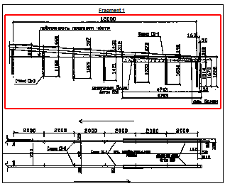
Setting the rectangular contour of the show boundary of the raster image |
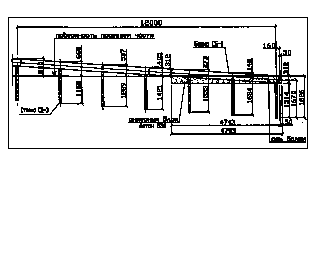
Displaying of the raster image after setting the show boundary |
|
|
|
The command prompts when setting the rectangular boundary:
|
Select block or X-references or [?]: |
Select raster and press ENTER. |
|
[Select_polyline /Polygonal/Rectangular] <Rectangular>: |
Press ENTER. |
|
Specify first corner: |
Specify the first corner. |
|
Specify opposite corner: |
Specify the opposite corner. |
The command prompts when setting the polygonal boundary:
|
Select block or X-references or [?]: |
Select raster and press ENTER. |
|
[Select_polyline /Polygonal/Rectangular] <Rectangular>: |
Select Polygonal. |
|
Specify first point: |
Specify the first point. |
|
Specify next point or [Undo]: |
Specify the second point. |
|
… |
… |
|
Specify next point or [Undo]: |
Specify the end point and press ENTER. |
The command prompts when specifying a boundary by a polyline:
|
Select block or X-references or [?]: |
Select raster and press ENTER. |
|
[Select_polyline /Polygonal/Rectangular] <Rectangular>: |
Choosez Select polyline. |
|
Select_polyline: |
Select the polyline.. |
To turn on/off the clipping contour:
1. In the Modify menu, click Clip and then the On or Off commands. 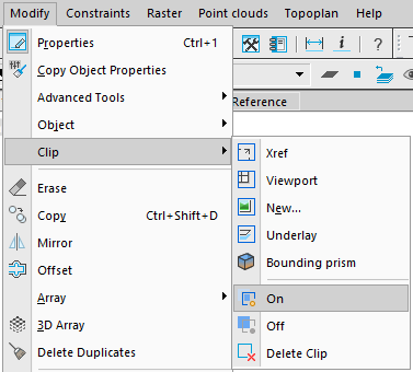
2. In reply to the prompt in the command line Select block or X-references or [?]: Select the raster image and press ENTER.
You can also switch the clip show in another way: select a raster image and switch Show Clipped option in the Properties bar.

To change the clipping contour:
1. In the Modify menu, click Clip and then the New command.
2. In reply to the prompt in the command line Select block or X-references or [?]: Select the raster image and press ENTER.
3. In reply to the prompt in the command line Delete old boundary(s)? [Yes/No] <Yes>: Select Yes or press ENTER.
4. In reply to the prompt in the command line [Select_polyline/Polygonal/Rectangular] <Rectangular>: Select the required option and set the new clipping contour.
Note! It is possible to create a new clipping contour if the old contour is deleted.
To delete the clipping contour:
1. In the Modify menu, click Clip and then the Delete command.
2. In reply to the prompt in the command line Select block or X-references or [?]: Select the raster image and press ENTER.