
 De
De 

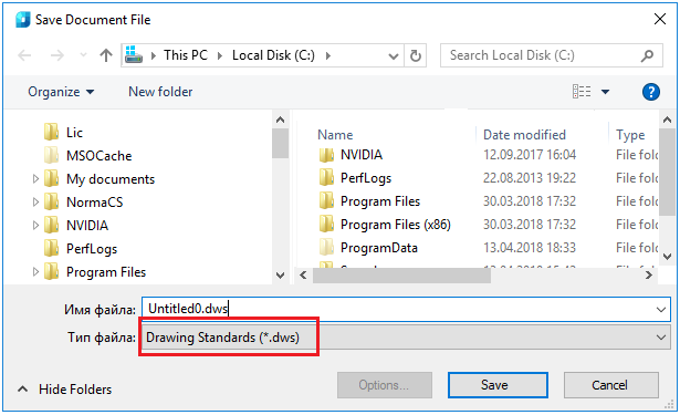
SETTINGS
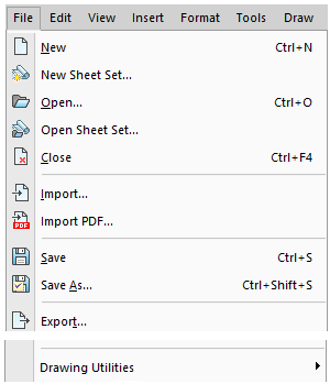
 Main menu: Tools -
  Design Settings....
Main menu: Construction- Settings....
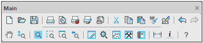
Toolbar: Settings... ( "Main").
 Command line: SPPARAMS, PARAMS.
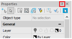
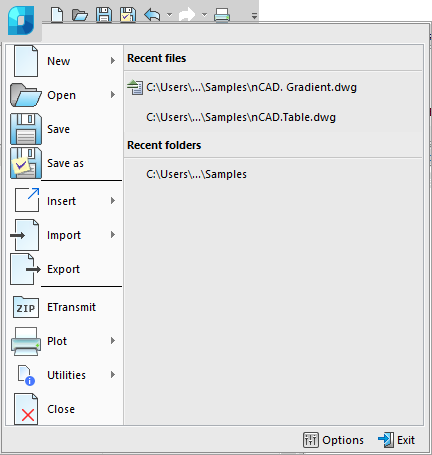
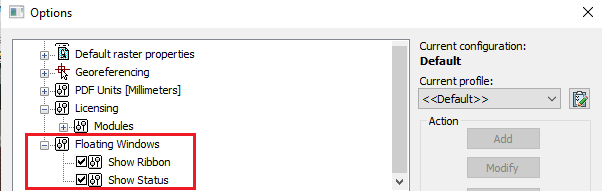
Customizing the interface and settings for design elements nanoCAD run in the dialog box nanoCAD Construction :

The header of the dialog displays the path to the settings file.
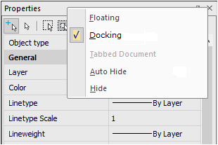
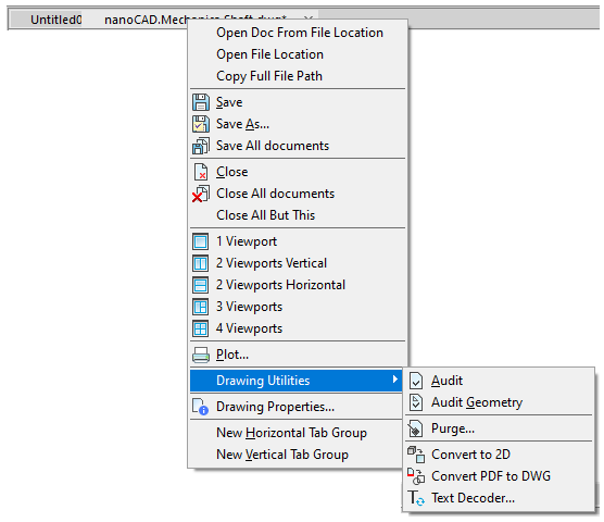
Menu "File" contains controls:
Save settings - saves changes to the current settings file.
Save settings as... - saves changes in settings to a new settings file.
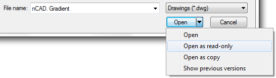
Load settings - loads settings from the specified file.
Types of uploaded files:
· Configuration files (*.xml)
· Skin Settings (*.cfg)
· Interface Settings (*.icf)
Configuration files *.cfg and *.icf used in nanoCAD Construction lower version 25 and contain settings that are currently stored in AppOptions.xml.
Restore start settings - loads settings preinstalled in nanoCAD Construction .
|
Important! |
The function of saving the settings, when the saved file is the same as the one already existing, does not overwrite the old file, but complements it. When changing the standard, for example, from the ESKD to ISO, both standards will be available in the settings file. |
Menu "Organisation"manages enterprise standard settings.

Enterprise Standard - a single configuration file (parameters, layers, profiles) for the enterprise. All settings are stored in one file.
In the settings dialog, the profiles table and the "Organisation" settings layers are highlighted in light gray.
Menu "Organisation" contains controls:
· Create organisation settings - command allows you to create a corporate settings file for subsequent transfer to other machines or for location on a shared server.
Creating the settings file:
1. After the command is called, a selection field appears next to each parameter and section.

2. You must specify (check) which settings will be included in organisation settings. Then click the "OK" button. The dialog box prompts you to enter the location and name of the corporate settings saving.
3. Indicate the path, name and confirm. A file with corporate settings will be created.
· Set settings file... - the assigned organisation settings settings file overrides the custom settings file AppOptions.xml. New documents will be created in accordance with the values in organisation settings settings file.
· Flush - command to refuse to use the organisation settings. In this case, the control file becomes the user settings file AppOptions.xml.
· Apply organisation settings to document - the command applies corporate settings to files created earlier or in another place that do not have these settings.
|
Important! |
The user can not delete layers and profiles of organization settings from the corresponding tables in the settings dialog. When saving settings with new values, they are saved only in the current document. The configuration settings in the organization settings file and the standards within the configuration must strictly correspond to the downloaded settings in the application. If there is a mismatch, the override of the settings will not work! |
Contains:
1. Tabs with settings settings:
· Symbols
· Forms
2. Graphic window for displaying custom parameters (not editable).
3. Container "Legend" with the legend of the kind of settings (not editable).

· Symbols - parameters with this background refer to the design parameters. In the nanoCAD Construction low version 25 settings are stored in the format files *.cfg
· Interface settings - parameters with this background refer to the interface parameters. In the nanoCAD Construction low version 25 settings are stored in the format files *.icf
· Organisation settings - parameters with this background indicate that they were downloaded from the Organization settings.
· Redefined value- parameters with this background indicate that they have been changed by the user.
4. The "Standard" container is intended for displaying the default development system of the design documentation (the choice is possible if there are more than one standards).
5. The "Save as defaults" container contains configuration items that indicate what will be saved by default when you click the "OK" button. Contains the selection field "Symbols".
The tab is used to configure the general parameters of the interface nanoCAD Construction .


It contains sections:


· Edit
· Design
· Hot keys


Current profile
Layer profiles are designed to organize the work of different departments of the enterprise over a single drawing file. Each user at the same time works with their group of layers, controlling their visibility by means nanoCAD.

Since the design of the drawing depends on the settings of the deployment of registration of the layers and the current profile of the drawing, then for each object type you want to specify in the settings option to be placed on the appropriate layer (for example, callouts given layer "Leaders")
Depending on the current profile to the layer name prefix will be added.

Thus, it is possible to group layers created by users with similar profiles (for example, the objects created by the designer - prefix "D_", and technologists - prefix "T_").
When adapting the distribution in the setup.ini file, you can assign a prefix in the parameter by default APP_OPTIONS_PROFILE.
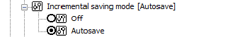
Execute command "Regenerate" on opening document
The command "Regenerate" whenever you open a document

Enable option "Use paper space units fo scaling" automatically
Automatically changes the setting nanoCAD Construction "Scale to paper space units" ("Use paper space units for scaling") for the types of lines.
Change current linetype scale
It enables or disables the scaling of line types in the standard objects when you change their size.
Use table of colors and weights
It enables or disables the use of the table of colors and weights. If enabled, you can use the standard colors from the table. "Compatibility Mode" - is used when working with documents created in early versions ofnanoCAD Construction .
Standard text weight
It standardizes the value of the weight of the text for all text in the document.
Color and line width
Is to set the standard design elements.

Decimal delimeter correction
· Do not correct decimal delimeter - does not perform any actions with a separator.
· Use dot '.' as decimal delimeter - automatically replaces the delimiter with a dot.
· Use system locale decimal delimeter -in this case, the separator will be replaced with the symbol set in the system settings.
Create an activate standard text and deimension styles in new documents
Managing the creation of standard styles. The default setting is "Yes". Specifying the value "No" allows you to create new documents without predefined standard dimensional styles.
|
Yes |
No |
|
|
|


Explode Block References under drawing design elements
Yes - when overlapping objects nanoCAD Construction blocks nanoCAD break up.
No - when overlapping objects nanoCAD Construction blocks nanoCAD masked with the command wipeout.
Enable enchanced grips
When this function is enabled, additional handles are displayed on the objects nanoCAD Construction .
Set associativity during insertion of object
By default, the setting is enabled. When you turn off, the binding of the inserted objects to the primitives is inactive.
Example with dimensions. If the setting is enabled, then, when setting the dimensions on the line, the size will be associated with the line. When you change the line, the size changes.


If the setting is turned off, only the line will change.

Use localized abbreviations of command keywords
Abbreviations for the keywords of the commands are described in the file with the extension .pgp and are located in the installation location nanoCAD Construction
Highlight color
The color of the highlighting of primitives, when their indication is required. For example, the line's highlight when specifying a size for the placement.
Automatically switch keyboard layout to local language
When you call dialogs with fields nanoCAD Construction automatically turns on the layout set in the system settings.
Show rectangle around objects
Display control of the frame around objects nanoCAD Construction and blocks nanoCAD.

When this option is enabled, scaling is turned off Shift+RBM.
Automatically turn of snaps: Nearest, Endpoint, Quadrant, Center
Temporarily includes bindings when inserting objects nanoCAD Construction .
With the option disabled, the "Direction" toolbar may not work correctly.
To show the toolbar "Direction" automatically
The "Direction" toolbar control that appears when you insert database objects and a number of drawing design teams.

Scale dimensions
Yes value:
1. The measurement scale specified in the "Dimensional Styles" on the "Primary units" tab is replaced by the measurement scale specified in the Design Settings - Main Options - Design.
2. The global scale specified in the "Dimension Styles" on the "Fit" tab is replaced by the design scale specified in the Design Settings - Main Options - Design.
The value is "No". The scale is not replaced.
Scale texts
The value is "Yes". When you change the scale using the Scale toolbar, the "Height" parameter in the "Text Format" dialog for the multi-line text and the command line for the single-line text proportionally changes.
The value is "No". When you zoom in using the Zoom toolbar, the Height option does not change.
Scale hatches
The value is "Yes". When zooming with the Scale toolbar, the Scale parameter in the Hatch dialog is proportionally changed.
The value is "No". When zooming with the Scale toolbar, the Scale option in the Hatch dialog does not change.
Ignored layers
Specifies layers nanoCAD, on which primitives will not overlap with objects nanoCAD Construction .
When you click on the ellipsis, the "Excluded Layers" dialog opens to edit the list of layers.
The dialog menu allows you to add a layer and enter it manually, delete a row with a layer or select a layer from the ones available in the drawing.
Unplotted layer
Specifies which layer the objects will be placed on nanoCAD Construction , which will not be printed.
Mini-toolbar for viewports
The nanoCAD Construction toolbar control that appears when you right-click inside the viewport.
If the option is off, then when you right-click inside the viewport nanoCAD the standard menu will be called up nanoCAD.
|
Yes |
No |
|
|
|
Show tooltips
Advanced Tooltip Management Tool (with hyperlink "Edit...") for objects nanoCAD Construction and blocks nanoCAD.
Show delay, ms
Tool to control the speed of the appearance of tooltips.
Hide delay, ms
Tool for managing the duration of the tooltip display.
Program objects
Sets the rule that when you double-click on object nanoCAD Construction , the editing dialog of this object will be called.
With the option disabled, the properties of the object are called.
Dimensions, Regular texts, Multi-texts
With the option enabled, double-clicking the left mouse button on the size brings up the editing dialog nanoCAD Construction .
With the option disabled, the properties of the object nanoCAD or edit dialog nanoCAD.
Use symbol scale
Changes the type of scaling:
· Yes - Drawing scale.
· On - Model scale.
More details in the description of work with the current scale.
Drawing scale
Sets the default scale of design elements and the scale of the types of geometry lines.
|
Note: |
The scale type of the dimension lines is reserved and is always 1 by default. |
Model scale
Sets the default measurement scale. The displayed value, which is set when dimensioning, increases in direct proportion to the scale value. For example, if you set the size of a 10 mm section and the measurement scale is 1:10, the displayed value is 100.
Text wipeout offset
Sets the standard indentation of the geometry marking from the text.
Using the example of a size marker. With a larger size, the square background overlaps the geometry.
|
0.2 |
1 |
|
|
|


Cut CAD-platform elements
"Wipeout" - closes the primitive.

"Cut" - cut the portion of the primitive. If you delete or move carved primitive returns its status.

"No" - It does not cover the primitive.
Enable hints
Tool tips display control.
This option does not apply to messages with the status "Error".
Avoid mouse pointer
When this option is enabled the message will be moved around the screen so as not to obstruct the selection.
Keyboard Assignment Tool for calling the quick settings dialog and the notification messages window.

Show <Quick Options> dialogue

Show notification window

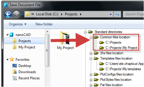
The database includes, in addition to standard elements, table and format templates, bolt assembly templates, groups and markers, as well as examples and other user elements. The choice of a specific database is determined by the configuration of the path to the data source.

Data Source
The database nanoCAD Construction 23 includes, in addition to standard elements, table and format templates, bolt assembly templates, groups and markers, as well as examples and other user elements. The choice of a specific database is determined by the configuration of the path to the data source.
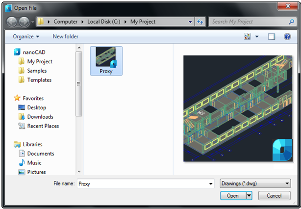
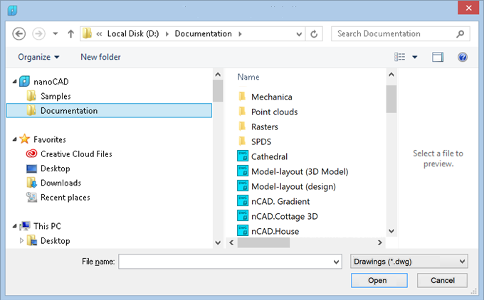
When you click on the button  in the "Data source" field, the dialog for specifying the data source appears.

nanoCAD Construction 23 provides work, both with local databases, and with the database on the MSSQL server.
If you are using an MS SQL database, you must select the "Data Source - MSSQL" radio button. In the "Server" field, specify the server name (along with the name of the SQL Database Server Instance). For example: SERVER, or SERVER\SQLEXPRESS. In the "Database" field, you must specify the name of the database to which you are connecting.
If you are using a local database,you must select the "Data Source - Local Database" radio button, and then specify the path to the database file.
As a local database for computers with the x32 bit capacity, format files *.mcs (MS Access).
As a local database for computers with the x64 bit capacity, format files *.mdf (LocalDB, for Windows Vista and higher).
Required drivers are installed automatically when installed nanoCAD Construction 23.
By default, with a local installation, the database is located in the folder %programdata%\nanosoft\nanoCAD Construction 237.0\DataRW\.
Picture size
The size of the preview image for the database elements in pixels.
|
70 |
140 |
|
|
|
Select object in browser
· Single click
· Dowble click
Use only these standarts from the library
Restricting the used standards filter.
Filter of nomenclature
To limit the selection of parts from the catalog of standard and standardized products nanoCAD Construction 23 it is possible to automatically filter the database using nomenclature filters.
To enable and configure a nomenclature filter, you must enable this feature in the settings nanoCAD Construction 23.
The filter editor is called by pressing the button with the ellipsis. As a result, the settings window of the nomenclature filter appears:

In the upper part of the window there are buttons for creating, downloading and saving files of the nomenclature filters, as well as a switch for enabling / disabling database filtering according to the selected filter. nanoCAD Construction 23 allows you to switch between different filters and temporarily turn them off.
The structure of the database is displayed in the left part of the window nanoCAD Construction 23, the icons of which show the current state of each element of the database:
 - the standard icon of the database element. Indicates that all sizes and the element itself are allowed to be used.
 - prohibition to use icon. Indicates that this element is not allowed to be used.
 - partial use icon. Indicates that this element is allowed for use with a limited set of standard sizes.
To enable / disable the use of the entire element, use the "Allow part use" switch. To disable a specific part size, you must uncheck the column ID of a line of this size in the part dimension table.
|
Note: |
Database access settings are interface settings. If you use data compression on a disk, you may experience problems connecting to local databases (for x64 versions). |
The tab is used to configure standard elementsnanoCAD Construction .

The control display color selection standard elements when they are selected, the automatic installation of dependencies.
The color display can be selected from a set and the built-in color picker.
Control the display of invisible (hidden) lines of standard graphic elements.
The control display color selection invisible (hidden) lines of standard graphic elements.
The color display can be selected from a set and the built-in color picker.
Default layer for parametric objects
The control layer selection, which by default will be placed standard parts database.
A layer can be selected from the existing (previously created) or create a new layer in the same window.
The control layer selection, which by default will be placed holes created by the operation "Bolting".
A layer can be selected from the existing (previously created) or create a new layer in the same window.
How to set the hatching step, is used by default.
The control is used for the step of asking the values of the diameter and length of the shaft sections created using the "Spindles".
When you insert a section of the shaft the value of its length and diameter will be rounded up to a multiple grid spacing.
Control Using the "spacing".
If the grid is not used, the values of the diameter and length of the shaft portions are not rounded.
Highlight color for working planes
Highlight color for working planes
Curve colors travel, bend, torque, force, tension
Color control diagrams displayed in the calculation of gross.
The selected color is preserved when exporting diagrams in the drawing.
The color display can be selected from a standard set and set of built-in your palette.
Acceleration of gravity OX, OY, OZ
Set design parameters for the respective axes of acceleration of the shaft.
Control increments partition diagram plotted in the entire length.
Complementing the strength calculation of shaft reactions bearings.
Control the display of numerical values on the diagram exported to the drawing.
The values are displayed at the critical points of the shaft.
Sets the strength of the theory to calculate the equivalent stresses shafts.
Setting up layers for different elements of the standard, the size and type of stairs, and the appointment of templates to various reports nanoCAD Construction .
The names of the layers under the standard elements. After inserting a standard element, it will be placed on the appropriate layer is configured.

1. Linear break
2. Arrow size
3. Guiding line marker size: Without mark, Empty, Filled, Opaque
4. Size of mark

When forming report templates will be taken from the settings.

Set the storage address labels connectors in the base element.
Set the address tag storage paths in the database elements.
Set the address tag storage equipment in the base elements.
It allows you to configure the IFC objects disposable layer and color.
Tab "Symbols". Designed to customize the display of drawing symbols of nanoCAD Construction .

· Notes
· Symbols
· Holes
· Joints
Setting allows you to change the size of the layer, which is automatically updated with new dimensions and copied settings dialogs, etc.

Allows you to choose the layer,which by default will include new dimensions and copied.
When this option is copied dimensions will be placed on the drawing layer selected for size. When off, dimensions placed on the active layer.
Control built ordinate dimensions. If the option is used ordinate dimensions standard ISO, built-in platform nanoCAD. When this option is used ordinate dimensions nanoCAD Construction .


Open a dialog to automatically
Control automatic opening dialogue sizes.
Replaces used in nanoCAD arrows in dimensional chains. There is a possibility to replace the serifs, or replace point at all.
Spreadsheet template tolerances
Allows you to select a table template tolerances available in the database.

Settings of notes, such as text, arrows, pointers.

Allows you to choose the direction of oblique arrow in leader.


Show dialog before inserting the object
When this option is enabled, the dialogue is displayed before inserting note.

Align text line by current UCS
When this option is on, shelves of leaders are rotated by the User coordinate system.
When this option is enabled on inserting the following notes previously entered text remains in the input field.
The remaining options allow you to change the size of text, indexes, thickness, layer placement, color, etc.


Note for multilayered constructions

Settings of views, sections, detail views. It allow you to choose the layout for placing cuts and sections, color of symbols, text, size of text, lines, arrows.


Layer
Selection of the layer on which is located the node designation.
By clicking on the ellipsis to open the dialog "Table layers", where you can configure the layer.
Colour
The color of a node designation lines.
Line thickness
The thickness of the unit designation lines.
Diameter (d)
Text style
Text style node designation.
text height (a)
When the value of unfilled "Page" at installation site designations.
Text color
The color of the text node designation.
Vertical text indent (c)

Big text height (b)
When you empty the meaning of "Page" at installation site designations.

Layer
Selection of the layer on which is placed a fragment of the designation.
By clicking on the ellipsis to open the dialog "Table layers", where you can configure the layer.
Colour
Color designations fragment lines.
Line thickness
The thickness of the lines refer to the fragment.
Leader indent (c)
Radius (d)

Minimal leader length (e)

With a length of less than the specified callout, the text will be placed without bubbles.
|
More than the set value |
Less than the set value |
|
|
|

Text style
Text style notation fragment.
Text height (a)
Text color
The color of the text refer to the fragment.
Vertical text indent (b)


Layer
Selection of the layer on which is placed a marker position.
By clicking on the ellipsis to open the dialog "Table layers", where you can configure the layer.
Colour
Color positional marker lines.
Line thickness
Thickness positional marker lines.
Size (c)

Text style
Text Style node designation.
Text height (a)
Text color
The color of the text node designation.
Space around (b)


Layer
Selection of the layer on which is placed a marker changes.
By clicking on the ellipsis to open the dialog "Table layers", where you can configure the layer.
Color
The color of the marker line changes.
Line thickness
The thickness of the marker line changes.
Height factor
Attitude a/b

Snap angle
Step-lines to callouts.
Text style
Text Style marker changes.
Text height (a)

Text color
Text color marker changes.
Comment height (c)
Vertical text indent (b)
Horizontal indent (d)

Setup Menu icon designation position.

Setup menu icon gradient.

Settings of weld symbols allow you to change the layer for label placement, color, style and size of lines and text.

Settings of boundary forms allow you to change the layer for label placement, color symbols, line thickness, and the dimensions of the various elements of the boundary shapes.

Settings of distribution range allow you to change the layer for label placement, color, size lines, arrows.

Settings for end markers allow you to change the layer for label placement, color and size designations.

Settings of elevation mark on the plane, that allow you to change the layer for label placement, color lines and text, lines, and text size.
Settings of symbol of Elevation mark, that allow you to change the layer for label placement, color lines and text, lines, and text size.

Settings of stationing.

If enabled, shows dialogue before inserting the stationing symbol.
Settings of construction axes, that allow you to change the layer for label placement, color lines and text, size markers, axial lines, arrows.
Settings of construction axes array. It allows you to change the location of the construction axes, place symbols, color, size and style of text and lines.

When this option is enabled, each following array of axes will use the parameters of the previous.
When this option is enabled, array created will be split to individual axes.
Settings of objects similar to axis. It allows you to change the weight and color of the line, as well as a layer.

Settings of holes that allow you to change the layer for label placement, text style, size and color of the text, etc.

Settings of break lines,that allow you to change the layer for label placement, color, and line sizes, type of fracture lines, etc.

Settings of symbols of permanent connections, that allow you to change the layer, label placement, color, size, style, text and lines.

Menu tab "Forms". Designed for setting up the parameters of parts of the text tools to create a standard layout elements.
It contains the following sections:
· Table
· Notebook
Settings of the tables in nanoCAD Construction .

Specifies layer for placing tables.
Sets color of table elements.
Allows you to choose the thickness of the lines of text in the table.
Option "by layer" sets the line width from the layer it is placed (default value).
Option "By block" sets the line width for by the block in which it is included.
Option "By object" sets the line width individually using properties palette.
Selecting "Default" sets the default line thickness for the table.
You can also set the line width of a standard set of values.
Sets the default text style in the table
Allows you to choose the standard text height.
Control choice of color of text in tables.
Allows you to choose the thickness of the lines of text in the table.
Option "by layer" sets the line width from the layer it is placed (default value).
Option "By block" sets the line width for by the block in which it is included.
Option "By object" sets the line width individually using properties palette.
Selecting "Default" sets the default line thickness for the table.
You can also set the line width of a standard set of values.
Sets width factor for text in table cells.
Sets text indent in table cells.
Settings for drawing borders in nanoCAD Construction

Allows you to select the layer for the drawing border.
Sets the default text style within the drawing border.
Inventory fields of the next sheets
Enables placing of inventory title blocks on drawing border.
Create viewport in paper space
Creates a viewport when drawing border is inserted on the sheet.
It specifies settings of text of the technical requirements of nanoCAD Construction .

Sets the default line spacing in the text of the technical requirements.
Sets a default text height.
Sets a default value of the slope of the text in degrees.
Sets color of text in technical requirements
Sets the default text style specifications.
Sets a default value of header height in technical requirements.
Sets a default value of the header oblique angle in degrees.
Sets color of header
Sets the default header style.
Aligns the heading of technical requirements for the title block.
Sets the standard layer to accommodate the technical requirements.
Designations indicate areas near to the position
Automatically inserts lettering area next to the item number.
Sets the value of the indentation from the left edge of the title block horizontally.
Sets the offset value from the main vertical lettering.
Settings for notebook in nanoCAD Construction 23.

Specifies the path to the notebook.
Additional information on configuring the notebook here.
The tab is used to configure 3D settings nanoCAD Construction . The tab is available with a license for 3D.

· 2D views
Automatically project edges on sketch
The parameter when adding a new sketch adjusts the display of the projection of the edges of a flat face taken as the working plane for the sketch.
Call command "Add planar sketch".
Specify a flat face as a work plane.

Depending on the setting, a projection will be added to the sketch.
|
Yes |
No |
|
|
|


Automatically project the origin point on new sketch
Controls the projection of the origin point when creating a new sketch.
|
Yes |
No |
|
|
|
Automatically correct UCS while editing block references with 2D constraints
Automatic correction of UCS when editing a block reference with 2D constraints.
Restory viewport's camera while exiting 2D sketch editing mode
If enabled, the view camera will be in position before the sketch is edited.
Edit parametric constraint value upon creation
Controls whether the dependency editing dialog is opened immediately after installation.
Associativity for new bodies
The enabled option allows you to build fixed bodies without the possibility of defixation. The sketch must be attached to some plane.
Layer for sketches
It allows you to customize the name of the layer on which will be placed flat sketches.
Layer for working objects
It allows you to customize the name of the layer on which the objects will be located.
Layer for sections
It allows you to customize the name of the layer on which section will be located.
Layer for parametric 3D solids
Allows you to set the name of the layer on which the parametric 3D bodies will be located.
Show/no thread helix
Controls the display of the thread helix.
Thread helix color
Thread helix color.
Thread face color
Thread face color.
Mass display accuracy
Mass display accuracy for inspector properties and part and assembly unit properties.

Automatic update
Sets the update mode 2D views
Layer
It defines the layer which will be located 2D views
Show on sections
Adjusts the image visible lines on sections
Line color
Specifies the color of visible lines
Linetype
Specify the type of visible lines
Lineweight
It determines the weight of visible lines
Show on sections
It adjusts the display of invisible lines on 2D views
Line color
Specifies the color of hidden lines
Linetype
Specify the type of hidden lines
Lineweight
It determines the weight of invisible lines
Settings differ from visible
It determines whether the parameters are different boundary lines of the section visible lines
If not, the next line settings are not valid.
Line color
Specifies the color of the boundary line section
Linetype
Specifies the type of the boundary line section
Lineweight
It determines the weight of the boundary line section
Show
It controls the display of hatching
Face hatch
Settings such as shading

Show
It controls the display of hatching.
Face hatch
Settings such as shading.
Surface transparency
Settings such as shading. Default 0 - full transparency.
C:\Program Files\Nanosoft\nanoCAD Construction 23\mg11\ McConfiguration.exe
The utility is designed to manage a database of parametric objects of nanoCAD Construction 23.
The choice of a particular database depends on the size of the organization and the number of licenses used in it.
If the application is used in a large organization that uses a lot of licenses nanoCAD Construction , it is advisable to store the database on one server(MSSQL). Any change to the database will be immediately available to all users.
If you have multiple licenses in your organization, or you can not maintain the server, it is advisable to use local databases without using a server. The configuration utility allows you to connect files *.mcs - for win32 and *.mdf - for win64 (on Windows Vista and higher). Updating the database on different machines will have to be done manually.

Creating and restoring the database
Restore
Creates the database MS SQL Server from a backup created earlier. File "std.mdf" from the distribution as an archive does not fit.
For initial creation of a database it is possible to use a file of a backup of a database published on spds.ru.
When you select a command, a dialog appears "Select Data Source".
In this dialog, specify the machine name and the name of the Instance of SQL Server on this machine,which is supposed to restore the database. The desired values can be entered manually, or choose from a list of SQL Server present on the local subnet.
|
Important! |
To restore a database, you have access to it and have sufficient rights established by the administration of SQL Server |
In the "Database" must specify a new database name standard nanoCAD Construction 23, and then click "OK".
In field "Path to backup file (relative to server):" appears enter the relative path to the database. It must be a local path (UNC is not supported).
Note that when restoring a database on the server (different machine from the one that runs the configuration utility), database backup file must also reside on the server. This is necessary to ensure that SQL Server account have the right to recover the database from the specified file.
When you click on "OK" to start the recovery process (restore) the database.
In the menu of the current database, use the following commands:
|
Important! |
You should not use administrative tools SQL Server (Enterprise Management or SQL Management Studio) to restore the database from a file archive created by archiving of the configuration utility |
The path to the current database.

By clicking on the button  opens a dialog "Select Data Source" to specify the server and database.
In the dialog box, you can select the type of data source:
· MSSQL - The server and database fields are filled in.
· Local base - The file on the disk is selected. The format of the local database files can be mcs(Access) and mdf(LocalDB).
This field contains the path to the current database in the form of:
SQL:<Server Name \ Name Instance>:<database name>
The field to the local database contains the absolute path to the database file.
|
Important! |
After specifying the database, the base control buttons will be available, depending on the type of database and access rights. |
Backup
Creates a file - a copy of the current SQL Server database for subsequent recovery. By pressing the button, a dialog appears to specify a relative path to the file archive database.
Clicking on "OK" will create an archive file.
Repair
Fixes corrupted database.
Users
Allows you to edit user rights (to run, you need to have the appropriate rights).
The following templates are right:
User - sees only system and its objects. Edits only its objects.
Editor - sees only system and its objects. Edits only its objects. Has the right to publish its objects.
Administrator - sees all the objects in the database. Has the rights to edit all objects and publish them.
Filter selects from the list of users on the typed letters contained in the user name. The list can be sorted by attributes, for this click on the column headings.
View
Starts window browser base, where you can modify the database structure:
· Delete and move folders and objects;
· Import and export objects (it is possible to import multiple files at once);
· Publication and editing objects;
· Create shortcuts;
· Renaming, editing notes, setting the preview pictures.
Synchronize
Open dialog "Database Management".
This utility is designed to provide an update target databases from the source. Through it may be, for example, to update the local database sections or individual users with respect to a single central database Company (located, for example, on a server).
To synchronize the database to choose:
Target database - this database to be updated;
Source database - this update source.
By clicking on the button opens a dialog "Select Data Source" to specify the server and database.
In the dialog box, you can select the type of data source:
· MSSQL - The server and database fields are filled in.
· Local base - The file on the disk is selected. The format of the local database files can be mcs(Access) and mdf(LocalDB).
This field contains the path to the current database in the form of:
SQL:<Server Name \ Name Instance>:<database name>
The field to the local database contains the absolute path to the database file.
Database Synchronization:
· Synchronize only existing objects -in the target database will be updated only those objects that are present in the target database.
· Synchronize all - in the target database will be updated all the objects present in the original database (if the target object does not present, it will be created), object paths are set as in the original database.
· Synchronize and preserve path of existing objects - in the target database will be updated all the objects present in the original database (if the target object does not present, it will be created), the path to the objects that exist in the target database will be stored for no longer exist - will be created.
Synchronize by list of difference - synchronizes the database objects selected in the difference list.
Rewrite All - overwrites all database objects from the source database to the target database.
Skip 3d Models - do not modify the 3d model found in the database.
Synchronize GESN and ENIR - for the product "Construction Site": synchronizes the tables of the GESN and ENIR.
Button "Synchronize" synchronizes to the previously configured parameters. When synchronizing, it imports from the target database to the source database based on the specified synchronization parameters. When you import, only those objects will be updated, the modification date of which in the source database is later than the modification date in the target database.
Procedure for updating nanoCAD Construction .
On the SQL-server there is a database of enterprise details containing user-defined elements. The company received an update nanoCAD Construction , including an updated backup of the database.
To update the database correctly, you must:
1. Run the Configuration Utility.
2. Restore the update database nanoCAD Construction from a backup.
3. Press button "Synchronize", a dialog will open. Analyze the list of differences of objects in the current database and in the update, for which in the "Synchronize" dialog it is necessary to click on the button "Diff list". All necessary facilities (concerns standard objects nanoCAD Construction , change of which is not required) export, and after synchronization - import into an already updated database.
4. In the dialogue "Synchronize" select the type of synchronization "Synchronize all" and press button "Synchronize":
4.1. User objects created in the database will be saved when they are synchronized.
4.2. Modified standard objects nanoCAD Construction will be merged. When synchronizing, each different item will be analyzed - if a new view is added - it will be saved, if the script is changed, for example - the date of changes in the current database and in the update will be compared, a newer script will remain. Thus, these details merge, and if they are present and different in both bases, the new ones are taken.
Configuration Utility (system data)
Tab "Computer" is designed to collect data about the hardware of the computer running the utility.

To display information simply click "Read configuration".
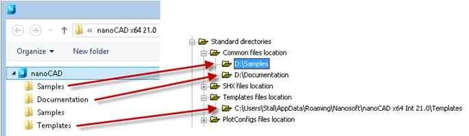
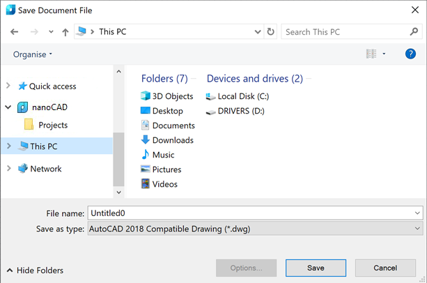
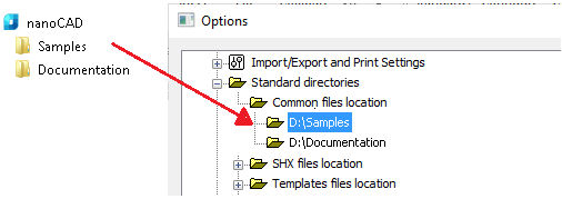
Transfer settings to another computer
Custom settings files are located in the folder
%APPDATA%\Nanosoft\nanoCAD Construction 23\ru-RU\AllOptions.xml - configuration file nanoCAD
To transfer settings, you must copy these files to the appropriate folders, and then in the settings nanoCAD Construction 23 specify the path to the settings for the design elements.
The application database is located along the following path:
%programdata%\Nanosoft\nanoCAD Construction 23\DataRW\std.mcs
User objects stored in the local database must be exported or transferred as part of the entire database.
|
Important! |
The function of saving the settings, when the saved file is the same as the one already existing, does not overwrite the old file, but complements it. I.e., when changing the standard, for example, from the ESKD to ISO, both standards will be available in the settings file. All changes to the profile table must be saved to the configuration file, otherwise these changes will only be displayed in the current work session. |
Objects nanoCAD Construction 23 when inserted, can be placed on a special layer.In this case, you do not need to pre-create the desired layer or make it the current one: the program will automatically do this regardless of the current layer.
In the settings of design elements, some objects have a parameter Layer.
Each time an insert is inserted, the object is placed on the current layer nanoCAD.
To change the object's insertion layer, select the desired layer in the list or write its name in the input field of the drop-down list:

You can also take advantage of Table of Layers, selecting an item in the layer selection drop-down list.

In the dialog box "Table of Layers" a list of the layers available for use is given.
 the symbol in the "On driwing" column indicates the layers that are present in the current drawing.
Button " New Layer" adds a new layer to the table.
Button " Delete Layer" removes the selected layer from the table.
Layer Profiles used when working together on drawings. Profiles allow you to automatically add a prefix to the names of the layers used to insert objects nanoCAD Construction 23.
To add and edit profiles, use the button  in the parameter line "Current profile" dialog box "Settings", tab "Main options".
In the dialog box Table of profiles lists available profiles.
Button "Add profile" adds a new profile to the table.
Button "Delete profile" removes the selected profile from the table.
Add a profile, select it in the table and close the dialog with the OK button. Close the dialog box "Settings".
When inserting objects nanoCAD Construction 23to the special layer, a prefix corresponding to the current profile will be added to the layer name:
|
Important! |
The function of saving the settings, when the saved file is the same as the one already existing, does not overwrite the old file, but complements it. I.e., when changing the standard, for example, from the ESKD to ISO, both standards will be available in the settings file. All changes to the profile table must be saved to the configuration file, otherwise these changes will only be displayed in the current work session. |
Command line: SPSETGOST.
This command is required to create (override) dimension style, text style and line types in accordance with the standards of environmentnanoCAD Construction for further work correctly.
Using this command can take in two cases:
1. If the file was not created in the environment nanoCAD Construction
2. Dimension styles, text styles, or types of lines have been changed by hand and requires their recovery.
Shortcuts for calling quick settings are set by setting hotkeys:

The Quick Settings dialog contains the following items:

· Current profile - indicates the current profile.
· Automatically turn on snaps: Nearest, Endpoint, Quadrant, Center - when you insert objects from the binding database, they automatically trigger.
· Show invisible lines - displays and hides invisible lines of standard parts hidden with the "Alt+RBM".
· Grid step - step of changing the diameter and length of a section of the shaft with its dynamic rendering.
· Use grid - to use or not to use a grid snap when dynamically rendering a portion of a shaft.