
 De
De  Es
Es  Fr
Fr 

-
-
-
-
-
-
-
-
-
-
-
-
-
-
-
-
-
-
-
-
-
-
-
-
2D Arrays
-
-
-
-
-
-
-
-
-
-
-
-
-
-
-
-
-
-
-
-
-
-
-
-
-
-
-
2D Arrays
2D Arrays
 Command line: AR, ARRAYCLASSIC
Array command opens the Array dialog box.
There is the  Select objects command in the top corner of the dialog box; it temporarily closes the dialog box whilst selecting the source objects. There is a line showing the number of selected objects - Objects selected below the button.
There is a preview window below the line.
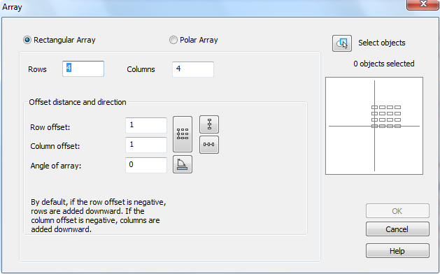
Parameters:
|
Rectangular array |
Switches on the rectangular array mode. |
|
Rows: |
Number of rows. |
|
Columns: |
Number of columns. |
Offset distance and direction
|
Row offset: |
Distance between rows. |
|
Column offset: |
Distance between columns. |
|
Angle of array: |
Field to enter an angle of array. |
|
Buttons: |
Button temporarily closes the dialog box to specify the distance or an angle on the screen. |
|
|
Specify the distance between rows on the screen. |
|
|
Specify the distance between columns on the screen. |
|
|
Specify the distance between rows and columns on the screen. |
|
|
Specify an angle of array on the screen. |


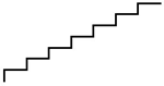
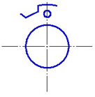
Example of creating stairs using rectangular array:
1. Create one more stair;
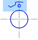
2. Select created objects;
3. Specify number of rows - 1;
4. Specify number of columns - 7;
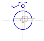
5. Specify distance between columns (specify point 1, after that point 2);
6. Specify angle (specify point 1, after that point 2);
|
Source stair |
Selection of objects |
Distance between columns |
Angle |
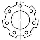
Result |
|
|
|
|
|
|


The More button opens an additional section of the dialog box to specify the base point of the X,Y axes.
Parameters:
|
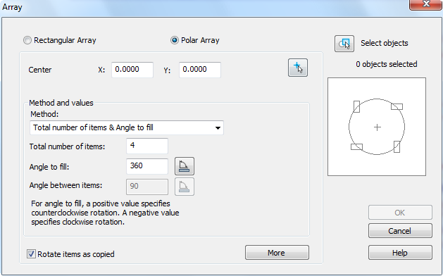
Polar array |
Switches on the polar array mode. |
|
Center point: X: Y: |
Fields to enter the X, Y coordinates of the array center. |
|
|
Button temporarily closes the dialog box to specify the center of the array on the screen. |

Method and values
|
Method: |
A drop-down list to select the method of array creation. Available options in the drop-down list: · Total number of items & Angle to fill · Total number of items & Angle between items · Angle to fill & Angle between items |
|
Total number of items: |
Number of elements (with source object). |
|
Angle to fill: |
Angle of array fill. |
|
|
Button temporarily closes the dialog box to specify the fill angle on the screen. |
|
Angle between items: |
Angle between neighboring array items. |
|
|
Button temporarily closes the dialog box to specify the angle between neighboring array items. |
|
Rotate items as copied |
Switches on/off the mode for rotating the elements in the array. |
|
More/Less |
This button opens/closes an additional part of the dialog box. |
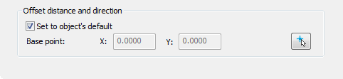
Offset distance and direction
|
Set to object’s default |
Switches on/off the mode for specifying the base point. |
|
Base point: X: Y: |
Fields to enter the X,Y coordinates of the base point. |
|
|
Button temporarily closes the dialog box to specify the base point on the screen. |
Example of creating polar array:
|
Source objects |
Selection of objects |
Center of array |
Result |
|
|
|
|
|
ARRAY Command (non-dialog option)
 Command line: - AR, -ARRAY
Creates non-associative 2D arrays using the command line.
Command options:
|
Select objects or [?]: |
Selects objects to be used in the array. The request appears if the objects were not pre-selected before starting the command. Press ENTER when you have completed your selection. |
|
? |
Calls additional options for selecting objects. |
|
Rectangular |
Creates an array of selected objects by orderly placing their copies at the nodes of a specified rectangular grid. |
|
Polar |
Creates an array of selected objects by orderly placing copies of them around a central point. |
Command options in rectangular array creation mode:
|
Enter the number of rows (---) <4>: |
Enters the number of rows (integer from 1 to32767). |
|
Enter the number of columns (|||) <4>: |
Enters the number of columns (an integer from 1 to 32767). If the number of rows is 1, the number of columns must be at least 2, and vice versa. |
|
Enter distance betweeen rows (---) <1>: |
Specifies the distance between rows, including the object length. If you enter a negative number, copies of objects will be located below the original. Instead of distances between rows and columns, you can enter the coordinates of points (2 values), then the distances will be determined by a rectangle constructed by two opposite points. After entering the coordinates of the first point in the command line, the Second point prompt will appear |
|
Enter distance between columns (|||) <1>: |
Specifies the distance between columns, including the object length. If you enter a negative number, copies of objects will be located to the left of the original. |
Command options in circular array creation mode:
|
Enter array center or [Base]: |
Specifies the coordinates of the central point – the point around which the array elements are distributed. Options: Base – Resets the base point of the object - the point that remains at a constant distance from the center point when constructing the array. |
|
Enter the number of items in the array: |
Enters the number of elements in the array, including the source object (an integer from 2 to 32767). If no value is entered, an array will be created based on the fill angle and element angle values. |
|
Specify the angle to fill (+= ccw, -= cw) [360]: |
Specifies the angle between the base points of the first and last array items. A positive value specifies counterclockwise rotation, a negative value specifies clockwise rotation. |
|
Angle between items: |
Specifies the angle between two adjacent array items if the number of elements in the array has not been specified. |
|
Rotate arrayed objects [Yes/No] <Yes>: |
Enables/disables the mode of rotating elements relative to the center point of the array. |