
 De
De  Es
Es  Fr
Fr 

-
-
-
-
-
-
-
-
-
-
-
-
-
-
-
-
-
-
-
-
-
-
-
-
-
-
-
-
-
-
-
-
-
-
-
-
-
-
-
-
-
-
-
-
-
-
2D Slope
-
-
-
-
-
-
-
2D Slope
 Ribbon: Topoplan – Relief >
  2D Slope
Menu: Topoplan – Relief >  2D Slope
Toolbar: Relief > 2D Slope
 Command line: NG_CREATE_SLOPE
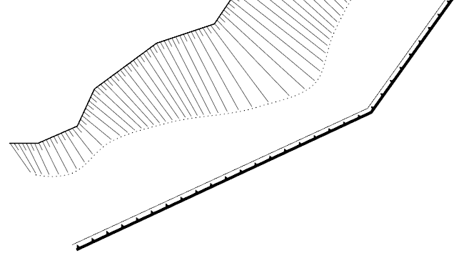
The command makes it possible to build various types of signs for slopes, cliffs, retaining walls:
· Unfortified slope;
· Fortified slope;
· Steep coast with a beach;
· Steep coast without beach;
· Stone retaining walls;
· Wooden retaining walls;
· Ground cliff.
Before starting execution, the command checks the set topographic scale and offers to switch to the 2D Wireframe visual style.

After running the command, set the slope type and characteristics in the Properties bar. The options vary depending on the type of slope and the way the edge is specified.
Options:
|
Slope sign |
Selecting the slope type: · Unfortified slope; · Fortified slope; · Steep coast with a beach; · Steep coast without beach; · Stone retaining walls; · Wooden retaining walls; · Ground cliff. |
|
Specify slope edges |
Selecting the method for specifying the location of the slope in the drawing: · onScreen – slope boundaries should be drawn manually on the screen; · Selection – line objects that will define the lower and upper edge of the slope should be selected in the drawing field. The top and bottom slope edges can be closed lines.
|
|
Smooth top of slope |
Specify whether the top of the slope should be drawn from point to point as a polyline or a smooth line. The parameter is available for certain slopes, when the method for specifying the slope edge is onScreen. |
|
Smooth bottom of slope |
Specify whether the bottom of the slope should be drawn from point to point as a polyline or a smooth line. The parameter is available for certain slopes, when the method of specifying the slope edge is onScreen. |
|
Draw bottom line |
Specify whether the bottom slope line is required. The parameter is available for certain slopes, when the method of specifying the slope edge is Selection. |
|
Layer of slope |
The layer on which the slope should be placed. |
Command prompts:
|
Apply changes? <Yes> or [Yes/No]: |
Yes – slope, cliff or retaining wall will be created with the current settings. No – if the settings have been changed, they will not be saved. The slope will be created with the settings displayed immediately after running the command. |
|
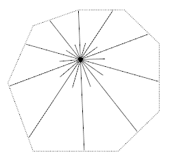
Specify points of slope top or [Peak]: |
Specify the first point of the top edge of the slope, or select the Peak option to build the slope from a single top point (hill). |
|
Specify slope peak point: |
Specify a slope peak point to build a slope from one top point (hill).
|
|
Specify points of slope top or [Undo/ClosePeak]: |
Specify the second and subsequent peaks of the slope top. Undo – undo the entry of the last specified peak. ClosePeak – close the line of the slope top. |
|
Specify points of bottom slope or [Undo/Close]: |
Specify vertices of the slope bottom. Undo – undo the entry of the last specified vertex. Close – close the line of the slope bottom. |
|
Select top slope polyline or [?]: |
Specify a polyline on the screen to build the top edge of the slope based on it. |
|
Select bottom slope polyline or [?]: |
Specify a polyline on the screen to build the bottom edge of the slope based on it. |
To create a slope, cliff, retaining wall:
1. Set the desired topographic scale and switch to the 2D Wireframe visual style.
2. Run the command.
3. Set the slope type and characteristics on the Properties bar. The options vary depending on the type of slope and how the edge is specified.
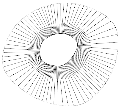
4. Specify the location of the slope on the drawing. Slope boundaries can be drawn manually, or created from existing drawing lines, depending on the value of the Specify slope edges option. The top and bottom slope edges can be closed lines. If you select the Peak option, you can create a slope from one top point (hill).
In the drawing, the slope is selected as a single set of objects, parts of which can be moved.