De
De  Es
Es  Fr
Fr 

Layers Dialog Box
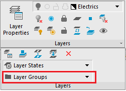
 Ribbon: Home – Layers >
  Layer Properties
Menu: Format –  Layers…
 Toolbar: Properties –
 Command line: LAYER, LAYERS
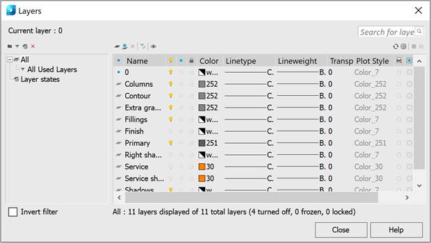
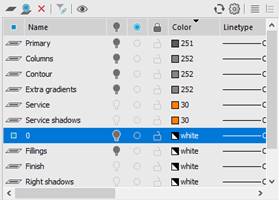
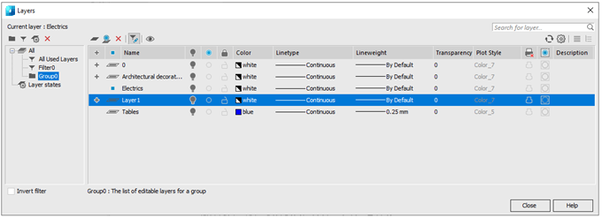
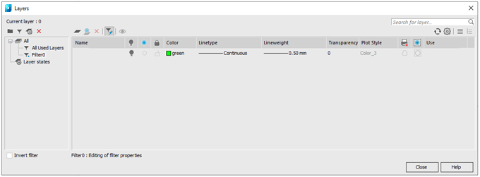
TheLayers dialog box is used to manage layers and their properties:
The Layers dialog is modal, that is, while the dialog is displayed on the screen, all relevant information on layers is displayed in it (and not on the functional bars) and changes outside the dialog are not taken into account.
There is a window in the left part of the dialog box with a category tree. In general, a category tree consists of the following elements:
· All
· All Used Layers
· All Layers without xrefs;
· External references
· Filters
· Groups
· Configurations
The right part of the dialog box shows the list of layers for the selected element in the category tree.
Below the dialog box title:
 – the current layer is shown.
|
|
Search for layer by name. |

Below the layer list box there is information about the displayed layers, the total number of layers and the number of disabled, frozen and locked layers.

Parameters:
Tree categories window
|
|
The button adds groups of layers. |
|
|
|
The button adds a filter. |
|
|
|
The button adds layer states. |
|
|
|
Delete |
The button deletes the tree’s elements. |
|
Remark: |
Short description of the layer’s configuration. The parameter is displayed above the Invert filter when you select the layer’s configuration in the tree. |
|
Invert filter |
The Inversion mode for the display of layers in the layer’s list. |
List of edited layers
Buttons
|
|
The button adds a new layer. |
|
|
|
Add Layer VP Frozen in All Viewports |
Adding a layer frozen in all viewports. |
|
|
The button deletes a selected layer |
|
|
|
The button edits selected filter. |
|
|
|
The button turns the single layer mode on. |
|
|
|
Refresh |
Regeneration |
|
|
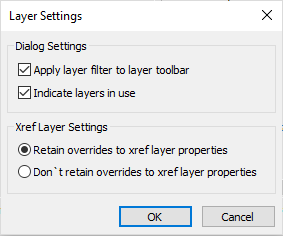
Layer settings |
Controlling the display parameters in the Layers dialog box and properties of layers included in xrefs.
Apply layer filter to layer toolbar – whether to consider or not the current filter when displaying the list of layers on the toolbar Indicate layers in use – whether to mark or not the used layers in the layer manager. Recalculation occurs when you open the manager, add/remove a layer. If this option is enabled, opening the layer manager on large files may take longer than expected. In previous versions of the program, recalculation was always performed.
Retain/Don’t retain overrides to xref layer properties – whether to retain or not the changes in properties of xref layers. |
|
|
Collapse Layer Filter Tree Expand Layer Filter Tree |
Buttons to control the display of layers filter tree. |


Columns
|
|
Column displays the current layer. |
|
|
Current layer |
|
|
Layer contains objects. |
|
|
Layer contains objects. Layer contains no objects. |
|
|
Xref layers. |
|
|
Layer contains objects and properties override is enabled in the viewport. |
|
Name |
Column displays the layer’s name. |
|
|
Column displays the icon for visibility of layers. |
|
|
Column displays the icon for freezing of layers. |
|
|
Column displays the icon for locking a layer. |
|
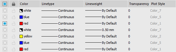
Color |
Column displays an icon for the layer’s color. |
|
Line Type |
Column displays the layer’s line type. |
|
Line weight |
Column displays the layer’s line weight. |
|
Transparency |
Displays the layer transparency. |
|
Plot style |
Column displays the layer’s plot style. |
|
|
Column displays the icon permitting printing. |
|
|
Column displays frozen layers in the current viewport. |
|
Description |
Short information about the layer. |


Double-click by the left mouse button on the column header separator automatically changes the columns width.
Layers in paper space
When working in paper space, a message appears in the title of the Layers dialog box –
When there is a current layout VIEWPORT, the title will look like - 
Columns with information about layers parameters in the viewport are added to the list of layers box.
|
|
Displays the icon of layer freeze in the current viewport. |
|
Viewport Color |
Displays the layer color in the current viewport. |
|
Viewport Linetype |
Displays the layer linetype in the current viewport. |
|
Viewport Lineweight |
Displays the layer lineweight in the current viewport. |
|
Viewport Transparency |
Displays the layer transparency in the current viewport. |
|
Viewport Plot style |
Displays the layer plat style in the current viewport. |
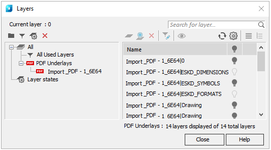
PDF Underlay layers
If PDF underlays are present in the drawing, information about them will appear in the categories tree.
If the selected PDF underlay contains layers, their list will be reflected in the dialog box. You can control visibility of underlay layers by turning the sign  on or off.
To Select Layers in the Dialog Box
Click on a layer to select it.
You can edit the parameters of several selected layers at once.
With SHIFT pressed, select the first and the last layer in the list. These layers and any layers between them will be selected.
With CTRL pressed, you can select individual layers from the list.
All layers in the list are selected by the Select all context menu command. The Unselect all command cancels the selection of all layers selected in the list.
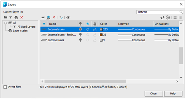
The Search for layer field in the top right part of the dialog box is designed for quick search for layers by name

To search for layers by name:
1. Enter text or part of the text in the field to search. You can use special symbols.
As you enter, only the elements the name of which contains the entered phrase remain in the list of layers.
The field button  resets the search results.
A list of layers can be sorted by any parameter. To sort a list of layers, click on the parameter column title.
For example, click on the Color title and all layers in the list are sorted by color. Clicking on the title again reverses the order of the sorted layers:
|
|
|
The sorting direction is indicated by the arrow in the header of the sorted parameter.
Specifying the Color, Type and Width of Lines in the Layer
In the Layers dialog it is possible to specify all the properties that can be inherited by the objects created on it. Ensure the By layer value is set in the corresponding boxes of the object properties.
Color, type and weight of lines can be specified for several layers at once:
1. Select a layer or several layers to change the properties.
2. Click on the required parameter in the column.
3. Select the value from the list.
A newly created layer has default properties. After a new layer is created, you can change its properties.
To create a layer:
1. Click button  Add.
Add.
A new layer with the name New Layer (N) appears in the list. The default name for the new layer can be changed.
To rename a layer:
1. Select layer in the dialog box.
2. Click name of the layer.
3. Enter the new name.
4. Press ENTER.
Only layers not used in the document can be deleted. The current layer, even if it is not used cannot be deleted.
To delete a layer:
1. Select layer in the dialog box.
2. Click the Delete  button.
3. You can delete several unused layers at once.
To delete several layers:
1. Select All Used Layers in the categories tree.
2. Switch on the Invert filter  parameter.
Select all sorted unused layers and select the Delete button or Delete command from the context menu.
1. Select layer(s) in layer list.
2. Click the Delete button.
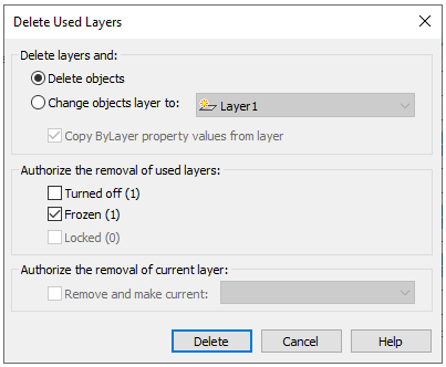
Delete used layers dialog box appears when you delete used layers:
|
Delete layers and: |
Selects the action with objects from deleted layer. |
|
Delete objects |
Deletes selected layer with all objects. |
|
Change objects layer to: |
Moves objects of deleted layer. Objects may be moved to new Layer№ or existing layer from the list. |
|
Copy ByLayer property values from layer |
Sets ByLayer properties for moved objects. |
|
Authorize the removal of used layers: |
Permits to delete Turned off, Frozen, Locked layers. Brackets show the number of selected layers with property. These options are available only if the layers being deleted contain these properties. The number of selected layer with this property is shown in brackets |
|
Authorize the removal of current layer |
Permits to delete the current layer. |
|
Remove and make current |
Selects the current layer from the list, when removing a previously set. |
3. click Delete.
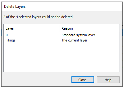
If the selection for deletion contains layers that cannot be deleted, information on them is presented in the Delete Layers dialog:
note You can delete the Defpoints service layer using the LAYDEL comamnd.
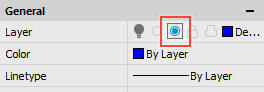
To make a layer active:
1. Select a layer in the Layers dialog box.
2. Click in the column icon of the selected layer. The  icon means that a layer is current.
Objects with visibility switched off are not displayed on layers and are unprintable, but are used in regeneration of a drawing. When layers are switched on/off, regeneration is not performed. It is recommended to switch on/off layers when you need to do it frequently and not for a long time. In other cases it is better to freeze them.
Visible layers are marked with icon. The  icon means that visibility of the layer is switched off. Visibility can be switched off for several layers at once. Visibility of the current layer cannot be switched off.
To switch on/off visibility of a layer:
1. Select one or several layers in the list.
2. Click the icon of any selected layer to switch them off
note: You can control visibility of drawing objects not only by switching visibility of the layer they lie on, but also directly by using the commands to hide and isolate objects.
Objects placed on frozen layers are not displayed on the screen and are unprintable and not used in regeneration of the drawing. You can freeze unused layers to make display and regeneration operations faster. But freezing a layer causes regeneration of the drawing, which takes time. Freeze layers if you only do it occasionally or you want to freeze the layers for a long time. In other cases it is better to switch them off.
Frozen layers are marked with  icon, while unfrozen layers are marked with
  .
.
You can freeze and unfreeze several layers at once. The current ( ) layer cannot be frozen.
Freezing or unfreezing a layer to edit it:
1. Select one or several layers in the list.
2. Click the icon of any selected layer to freeze them all.
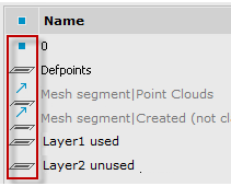
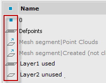
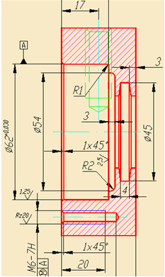
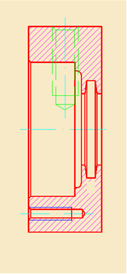
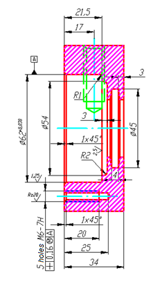
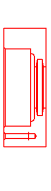
Freezing Layers in the Viewports of a Layout
Layers can be frozen in separate viewports of a layout. You can get different displays of the same objects in different viewports without creating additional geometry. For example, you create two layout viewports for the same object and freeze the layer with design elements in the second viewport:
Frozen layers from the current viewport are marked with  icon.
icon.
When the viewport is active, then icon is added to the Properties toolbar.
|
Viewport with unfrozen layers |
Viewport with frozen layer of design elements |
|
|
|
To freeze layers in a layout viewport:
1. Switch to layout with required viewport.
2. Double click this viewport to make it active.
3. Open the Layers dialog box and select all layers that should be frozen.
4. Click the icon of any selected layer to freeze the selected layers.
5. Close the Layers dialog box.
The layer will be frozen in the current viewport, but will remain unfrozen in all other layout viewports. It will not be printed only in this viewport.
To freeze a layer in all VPs:
1. Open the Layers dialog and select all the layers that should be frozen on all viewports.
2. Open the context menu by right-click on the selected layers and select the VP Freeze Layer > In All Viewports command.
3. Close the Layers dialog.
Layers will be frozen and invisible in all viewports.
To freeze a layer in all VPs except the current one:
1. Activate the viewport by double-clicking on it with the left mouse button.
2. Open the Layers dialog and select in it all the layers that should be frozen on all viewports except the current one.
3. Right-click on the selected layers to open the context menu and select the VP Freeze Layer > In All Viewports Except Current command.
4. Close the Layers dialog.
Layers will be frozen and invisible in all viewports except the current one.
You can also use the LAYVPI command to freeze a layer on all layout viewports except the current one.
To thaw a layer in all VPs:
1. Open the Layers dialog and select all the layers that should be thawed on all viewports.
2. Right-click on the selected layers to open the context menu and select the VP Thaw Layer in All Viewports command.
3. Close the Layers dialog.
The layers will be thawed and visible in all viewports of all layouts.
Command to manage frozen layers in individual viewports
Command line: VPLAYER
Command prompts and options:
Enter an option or [?/Freeze/Thaw/rEset/New_frozen_layers/Default visibility]:
|
? |
Shows the list of layers frozen in the selected viewport. |
Freeze – freezes layers in one or more viewports.
|
Enter layer name(s) to freeze or <specify layers by selected objects> |
Enter names of layers or select layer objects in the current viewport. |
|
Viewports [All/sElect/Current/Exclude current] <Current>: |
Select viewports for freezing specified layers. sElect option allows you to specify viewports in the drawing. |
Thaw – thaws one or more layers in one or more viewports.
|
Enter layer name(s) to thaw: |
ENTER names of layers. |
|
Viewports [All/sElect/Current/Exclude current] <Current>: |
Select viewports for thawing specified layers. sElect option allows you to specify viewports in the drawing. |
rEset – sets visibility of one or more layers in selected viewports according to default visibility of layers.
|
Enter layer name(s) to reset or <specify layers by object selection>: |
Enter names of layers or select layer objects in the current viewport. |
|
Viewports [All/sElect/Current/Exclude current] <Current>: |
Select viewports for resetting specified layers. sElect option allows you to specify viewports in the drawing. |
New frozen layers – creates new layers frozen in all viewports.
|
Eneter names of new layers frozen in all viewports: |
Enter names of layers. |
Default visibility – freezes or thaws specified layers for all new viewports.
|
Enter layer name(s) to change new viewports visibility <specify layers by object selection>: |
Enter names of layers or select layer objects in the current viewport. |
|
Visibility state in new viewports [Frozen/Thawed] <Thawed>: |
Select visibility state of selected layers in new viewports. |
Only two options are available in VPLAYER command for model space: New frozen layers and Default visibility.
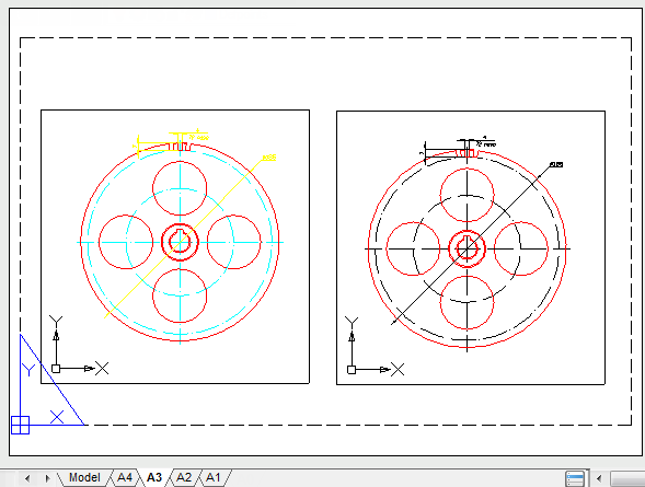
Redefinition of Layer’s Properties in Viewports
Redefinition of layer’s properties is a way to display objects in different viewports of layout with different properties (color, type and line weight) without changing properties with “ByLayer” or “ByBlock” values.
A color of axes lines is changed in the right viewport:
To redefine properties of a current viewport of a layout:
1. Double click this viewport to make it active.
2. Open the Layers dialog.
3. Select a layer from a list and change its parameters. You can redefine Color, Linetype, Lineweight and Transparency.
Parameters are changed only in the viewport of a layout. Other paper space viewports and the model space parameters are unchanged.
Layers with redefinitions of properties in viewports are highlighted in blue:
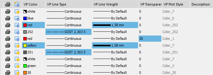
Removing redefinitions of properties of viewports layers
Remove Viewport Overrides for command in the context menu cancels redefinitions of layers’ properties in viewports
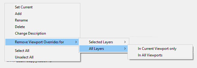
Command options:
|
Selected layers |
Cancels redefinitions of properties for layers selected in the dialog. Cancellation can be made: In Current Viewport only In all Viewports. |
|
All layers |
Cancels redefinitions of properties in all layers. Cancellation can be made: In Current Viewport only In all Viewports. |
If a layer is ulocked, you can create a new object on it. Objects created before locking are visible and they can be selected to view their properties, but they cannot be edited. You can snap to the object on a locked layer with an object snap. You can change the color, line type, weight type, make printable or unprintable on a locked layer.
Locked layers are marked with  icon.
icon.
You can lock or unlock several layers at once.
To lock/unblock layer:
1. Select one or several layers in the list.
2. Click on the lock column of the selected layer.
There is a mode to enable selection of objects on locked layers to view their properties and use object snap.
To select objects from locked layers:
In status bar click the  Selection from locked layers button.
Controlling Layer Printability
The contour  icon means that objects on the layer can be printed. Objects on the layers with
  icon will not be printed.
You can make several layers printable or unprintable at once.
To make layers printable or unprintable:
1. Select one or several layers in the list.
2. Click on the printability column of the selected layer.
View Mode of Selected Layers
Ribbon: Home – Layers >  Layer walk
Menu: Format – Layer tools >  Layer walk
Toolbar: Properties –
Command line: LAYWALK
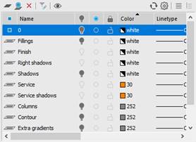
There is a mode to view only the selected layers in nanoCAD. Visibility of all layers in this mode, except the selected, are switched off automatically; visibility is restored when you close this mode. This mode is a quick alternative to switching off the visibility of all layers to display the content of one layer; it is very convenient if there are a lot of layers in the drawing.
|
All layer view mode |
Single layer view mode |
|
|
|
To switch on single layer or several layers view mode:
1. Click a layer to view in the dialog.
2. Select the Layer walk button, visibility of all layers, except the one selected, are temporarily turned off. Near the selected layer in the column the  icon is displayed. It means that this layer is visible.
3. Click other layers to view. Near the selected layers in the column the icon is displayed. It means that this layers are visible. Visibility of all layers, except the selected, is temporarily switched off.
4. Click on a visible layer (which marked with the icon) turns off its visibility.
With the Layers dialog box opened you can zoom and pan the drawing using the corresponding commands.
To restore visibility of all the layers, switch off the Layer walk button or close the Layers dialog box.
This mode is a quick alternative to switching off the visibility of all layers to edit the content of one layer. After selecting the mode, select any command and the Layers dialog box closes and the selected layer will be displayed. To restore the visibility of all layers after editing, open the Layers dialog box and the visibility of all layers is restored automatically.
Creating and Editing Group of Layers
The Layers dialog box allows merging of layers into groups. Grouping of layers is recommended when a document contains a lot of layers and you often need to change the settings of several layers; for example, to quickly block/unblock them or to control their printability.
One layer can belong to different groups.
Creation of a New Group of Layers
To create a group of layers for the entire document:
1. Select All in the categories tree.
2. Select the button  Add group and the button
  Show all layers (for group). To the left of the current layer icon column, the column
  for selecting layers for the groups is shown.
3. Enter a group name (the default name is Group…N, where N – is the number of the created group).
4. Select layers to make a group.
5. Select the Edit filter button to complete creating the group.
To add a subgroup of layers, select the existing group, in the context menu select the command Add > Group.
When adding new layers to a subgroup they are automatically added to all parent groups.
You cannot create a subgroup of layers for a filter.
To add or exclude layers from a group:
1. Select the group in the categories tree.
2. Select the Edit filter button.
3. In the column for selecting layers for groups, select the layers to form the group. Layers of the parent group are always selected.
The Layers ribbon group and the Layers2 toolbar contain a drop-down box to select states to restore from the list of existing ones.

A filter forms a list of layers that satisfy certain selection criteria. Selection in the filter is performed by one or several parameters of the layers; for example, selection of layers having a green color and line weight 0.50 which can be printed.
To create a layers filter for the whole document:
1. Select All in the categories tree.
2. Select the  Add filter button. The Edit property button is automatically selected.
3. Enter a filter name (a filter has a default name FilterN, where N is the number of the created filter).
4. In the Editing of properties of the filter window, specify the selection criteria for the layers in the filter.
5. Criteria, specified in one row are linked with the logical “AND”.
6. Criteria, specified in different rows are linked with the logical “OR”.
7. The Add and Delete buttons are used to add or delete rows of selection criteria.
8. Select the Edit property button to finish filter creation.
A layer’s name is often used as a selection criterion. Names can be specified as templates.
It is possible to use the following symbols in the template of a layer’s name:
|
Symbol in a template |
Corresponding symbols in a layer’s name |
|
|
* |
Asterisk |
Any sequence of symbols. |
|
? |
Question mark |
Any symbol. |
|
# |
Hash |
Any figure. |
|
@ |
At sign |
Any letter. |
|
. |
Point |
Any symbol except a letter or figure. |
|
~ |
Tilde |
Any sequence of symbols except the sequence after the tilde. |
|
[ ] |
Square brackets |
Any symbol except the symbols in brackets. |
|
[~] |
Tilde in square brackets |
Any symbol except the symbols in brackets. |
|
[-] |
Dash in square brackets |
Any symbol from the range starting with the symbol to the left of the dash and ending with the symbol to the right of the dash. |
|
` |
Backtick character |
Backtick character shows that the following symbol is an ordinary symbol and not special. |
If you select a group instead of the All element, a filter is created for the group.
To add to or exclude layers from a filter:
1. Select the All in the categories tree (to create a filter for all layers in the document) or a group (to create a filter only for the group).
2. Select the Edit property button.
3. In the Editing of properties of the filter window specify the selection criteria for layers in the filter.
4. Criteria, specified in one row are linked with the logical “AND”.
5. Criteria, specified in different rows are linked with the logical “OR”.
6. The Add and Delete buttons are used to add or delete rows of selection criteria.
7. Select the Edit property button to finish filter creation.
Criteria symbols to select layers for a filter:
|
|
Visible layer. |
|
|
Invisible layer. |
|
|
Frozen layer. |
|
|
Unfrozen layer. |
|
|
Locked layer. |
|
|
Unlocked layer. |
|
|
Layer available for printing. |
|
|
Layer unavailable for printing. |
|
|
Layer becomes unfrozen in new viewports. |
|
|
Layer becomes frozen in new viewports. |
|
|
Used layer. |
|
|
Unused layer. |


All nanoCAD documents contain a preset layers filter All used layers:

The filter shows all layers used in the current document. A filter does not show unused layers in a document. You cannot delete this filter.
All Layers without xrefs Filter
The preset layer filter All Layers without xrefs becomes available if a document contains layers with external references:
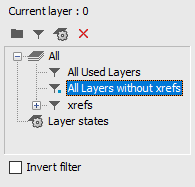
The filter selects all layers of the current document without external references. The filter does not display layers with external references. The filter cannot be deleted.
The Invert filter parameter below the categories tree can be used to display all the layers, which are not in the group, filter, external reference or configuration.
For example, to display all unused layers in a document, select the All used layers and select the Invert filter.
 .
.
When you deselect the Invert filter the list of layers recovers.
It is often needed to display layers of a particular category.
You can use the Invert filter for this:
1. Select a group or a filter in the categories tree.
2. Select the Invert filter.
3. Select all layers in the list and make them invisible.
Configurations of layers are backup copies of layers’ parameters.
Configurations are placed in the separate Configurations folder in the categories tree.
A configuration is created for all layers in the document.
To create a configuration, select the  Add configuration button. A new configuration has a default name – Configuration N, where N is the number of created configurations.
A created configuration can be edited, e.g. to change the parameters of its layers.
Configurations can be restored, renamed and deleted.
A recovery of a configuration places a copy of the parameters of the layer with the same name into the document; it means recovering the parameters of the layers and returning them to the moment the configuration was created.
Restore state
To recover a state, select Restore from the context menu of the state:
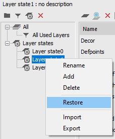
The properties of layers to be restored are selected in the Restore layer properties dialog box:
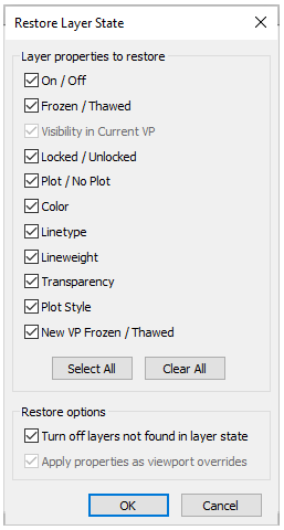
Layers added in a drawing after creating a state of layers and not saved in it can be turned off when restoring a state by checking the Turn off layers not found in layer state box.
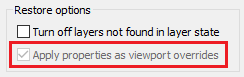
When restoring a layer state saved from the layout viewport, you can choose whether to use settings of such state as global properties of a drawing layers or as overrides for this viewport. The option Apply properties as viewport overrides is intended for this. Adding layers in a state
Adding layers in the configuration
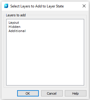
Layers that appeared in a document after creating a state, can be added in the state.
1. Select a state you need to add layers to.
2. Click the Add button or select Add in the context menu of the list of layers
3. Select layers to be added in the Select Layers to Add to Layer State dialog box, click OK.
Saves, restores and manages named states of layers.
You can call Layers state dialog with the following commands:
Ribbon: Home – Layers > 
Menu: Format – Layers state…
Command line: LAYERSTATE
Toolbar: Layers 2 –
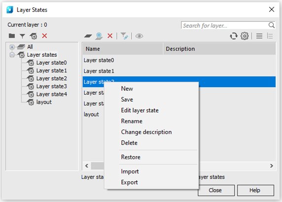
A state can be exported to LAS file and imported from LAS file or *.dwg file (Import and Export commands of the context menu). When importing, you will be prompted to restore the layer settings from the imported states.
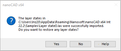
If you agree, the standard process of restoring the state will start, and the Restore Layer State dialog will appear, in which you should select the properties to be restored.
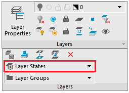
The Layers ribbon group and Layers 2 toolbar contain a window to select states to restore from the list of existing ones.
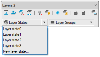
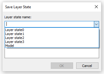
The command of the New layer state list allows for quick saving of layers settings in a new state without opening the Layers dialog box.
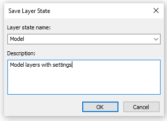
The Save Layer State list that opens allows for the possibility to save changes in already existing states: