De
De 

-
-
-
-
-
-
-
-
-
-
-
-
-
-
-
-
-
-
-
-
-
-
-
-
-
-
-
-
-
-
-
-
-
-
-
-
-
-
-
3D Slope
-
-
-
-
-
-
-
-
-
-
-
3D Slope
3D-Slope
 Ribbon: Topoplan – Relief >
  3D-Slope
 Menu: Topoplan – Relief >
  3D Slope
Toolbar: Relief > 3D-Slope
 Command line: NG_3D_SLOPE
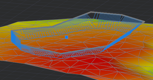
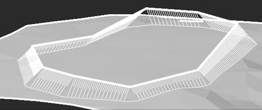
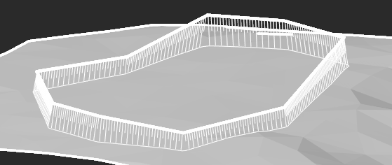
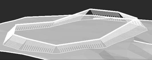
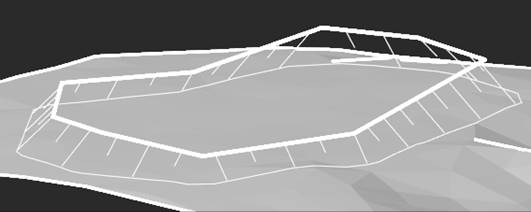
The 3D-Slope command creates a 3D slope from a surface or from existing objects.
After running the command, set the slope type and characteristics in the Properties bar. The options vary depending on the type of slope and the way the edge is specified.
Options:
|
Construction method |
Selecting the method for specifying the slope location, its parameters and objects on the basis of which it should be built: · Set Values – the slope will be created on the basis of one linear object (polyline, circle, segment or arc) specified as the top edge, according to the specified fixed values of the parameters (Slope Width, Slope Height, Slope Angle and Step); · From Object – a pair of linear objects (polyline, circle, segment, arc) should be selected in the drawing field, they will define the lower and upper edges of the slope. · From Surface – the slope will be created from the specified 3D polyline to the triangulated surface (TIN). The top and bottom slope edges can be closed lines. |
|
Width of slope |
A constant slope width measured from the edge defined by the linear drawing entity. |
|
Height of slope |
The height of the slope, measured from the edge defined by the linear drawing entity. |
|
Angle of slope |
The slope angle of the slope edge relative to the vertical axis. Can be specified between 0 and 90 degrees. The slope angle determines the size and position of the bottom edge of the slope. If you are building a slope to the surface, then the bottom edge of the slope should also be within the boundaries of the TIN.
|
|
Step of slope |
Step of the slope line.
|
|
Layer of slope |
Layer on which the slope should be placed. |
Command prompts:
|
Apply changes <Yes> or [Yes/No/saveDefault]: |
Yes – the slope will be created with the current settings. No – if the settings have been changed, they will not be saved. The slope will be created with the settings displayed immediately after running the command. saveDefault – save the default settings. |
|
Select polyline/ line/ circle/ arc or [?]: |
Select a linear object to define the edge of the slope: polyline, circle, line segment or arc. The polyline can be closed. |
|
Select first polyline/ line/ circle/ arc or [?]: |
Select a linear object to specify the first slope edge: polyline, circle, line, or arc. The polyline can be closed. |
|
Select second polyline/ line/ circle/ arc or [?]: |
Select a linear object of the same type as the first one to specify the second slope edge. |
|
Specify height of second edge: |
If both objects are at the same height relative to the XY plane, you will need to specify the height of the second slope edge. |
|
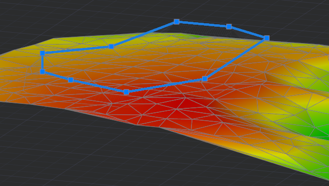
Select 3D-polyline: |
Specify a 3D polyline to define the top edge of the slope. The polyline should not extend beyond the boundaries of the TIN in the XY plane and lie above the triangulation surface. The 3D polyline can be closed. |
|
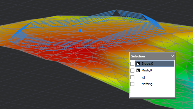
Specify direction of slope construction: |
Specify the direction of the slope edge bevel relative to the vertical line, i.e. the direction in which the Slope angle will be drawn.
|
|
Specify points of slope top or [Undo/Close]: |
Specify the vertices of the lower edge of the slope. Undo – cancel the input of the last specified vertex. Close – close the line of the lower edge of the slope. |
|
Select polyline of slope bottom or [?]: |
Specify a polyline on the screen to build the bottom edge of the slope based on it. |