
 De
De  Es
Es  Fr
Fr 

-
-
-
-
-
-
-
-
-
-
-
-
-
-
-
-
-
-
-
-
-
-
-
-
-
-
-
-
-
-
-
-
-
-
-
-
-
-
-
-
-
-
-
-
-
-
Conventional Signs
-
-
-
-
-
-
-
Conventional Signs
 Ribbon: Topoplan – Maps >
  Conventional signs
Menu: Topoplan – Maps >  Conventional signs
Toolbar: Maps > Conventional signs
 Command line: WS_CLASSIFICATOR
The Conventional signs functional bar is used to insert conventional signs into a drawing (for drawing topoplans of scales 1:500, 1:1000, 1:2000, 1:5000).
Before drawing conventional signs, select one of the topographic scales: 1:500, 1:1000, 1:2000 or 1:5000, in accordance with the required scale of the finished drawing.
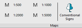
When changing the topographic scale, a proposal appears to change the scale for geopoints inserted into the drawing and the conventional signs of the classifier (blocks).
Appearance of the bar
The bar elements are structured:
· by thematic sections;
· In alphabetical order.
The letter T is used after the name for point Signs, for linear ones – letetr L. Signs consisting of segments in the form of a single line are created as Polylines objects, if the segments consist of several lines, then Multilines are created.
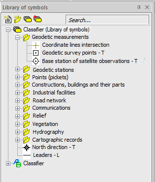
Search for a conventional sign
To quickly search for an element, you need to enter its name or part of the name in the upper text field of the bar. As you type, only those elements whose name contains the entered expression remain in the list of conventional signs.
Placing a conventional sign in a drawing
1. Double-click the left mouse button on an item in the list.
2. Specify the insertion point of the element in the working area of the drawing or enter its coordinates in the command line.
3. If you need to set paste options for the element, then enter them in the command line or in the dialog box that opens.
Point conventional signs – Specify the insertion point and enter attribute values, if any.
Linear conventional signs – sequentially set the points of a polyline/multiline in the drawing.
The capabilities of the Conventional signs bar are not limited to inserting signs from an existing classifier. It is also possible to create your own signs or connect third-party libraries. To do this, use the buttons at the top of the bar.
 Create element. Creating a new element of the library.
 Create section. Creating a folder for thematic ordering of library items.
 Create library. Prompts for a name in the command line and creates a new empty library with two ordering options: thematic and alphabetical.
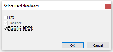
 Attach/detach library. Opens a dialog box that allows you to enable/disable the display of existing libraries in the Conventional signs bar. The source library cannot be disabled.
Work with the sign library is described in more detail in the Create library section.