
 De
De  Es
Es  Fr
Fr 

-
-
-
-
-
-
-
-
-
-
-
-
-
-
-
-
-
-
-
-
-
-
-
-
-
-
-
-
-
Tool Palettes
-
-
-
-
-
-
-
-
-
-
-
-
-
-
-
-
-
-
Tool Palettes
 Ribbon: Manage – Palettes >
  Tool Palettes
Menu: Tools –  Tool Palettes
Menu: View – Toolbars – Functional – Tool Palettes
Toolbar: Standard –
 Command line: TOOLPALETTES
Create and save own tools for frequently applied commands, blocks, hatches etc.
Tool is a command in the Tool Palettes Manager, it can carry property values (color, layer etc.). Tools are located in the tool palettes.
Tool palettes data files location is displayed in the Standard directories node of the Options window.
Each tool in the Tool Palettes Manager has an icon. Drag it to the drawing space or double-click to execute the command (block is inserted, hatch is created etc.). User tools can be exported to .xtp files and then transferred to another computer with import into nanoCAD.
Tool palettes allow the user to collect specialized tools for process design within a single project or within one department without any effort ensures uniform styles.
|
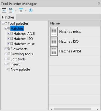
|
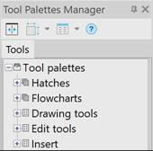
The Tool Palettes Manager functional bar displays a tree containing icons of tool palettes and tool palette groups. Root node initially named Tool Palettes. It has a context menu with the following items: Create group – creates a new group for storing tool palettes and nested groups; Create palette – creates a new palette for storing tools; Rename – renames the root node; Import palette... – imports a tool palette from .xtp file. |
There are three icons with the functions:
|
|
Configures the icon size (Small, Normal, Large). |
|
|
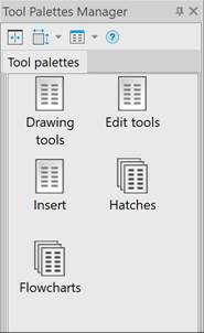
Selects an option of standard presentation of lists in the window (Icons, List, Details). |
|
|
Changes the active view option (tree or list). |


The  button switches between two active view modes: tree or list. The
  and
and  buttons are disabled in the tree mode. Dialog has a splitter (vertical dividing line) placed on the right in the tree mode and on the left in the list mode. Move the splitter to enter the view mode with display both tree and list.
Tool palette is a container for tools joined by user. A new empty palette can be created with the Create palette item of the context menu. You can drag palettes to move them inside the group. The Tool palettes bar can contain any number of tool sets with any names.
The tool palette node  has a context menu with the following items:
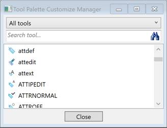
· Customize commands... – opens the Tool Palette Customize Manager dialog with nanoCAD commands list;
· Rename – renames tool palette;
· Sort by – sorts by feature (Name, Type);
· Move up — moves palette one position up;
· Move down — moves palette one position down;
· Remove – removes selected palette from the Tool Palettes Manager functional bar or from the group.
· Export – exports tool palette to .xtp file.
In the ToolPalette tree, you can create groups, which are similar to folders and can contain tool palettes and nested groups. To create a group that should be a child of the root node of the tree, you should use the Create group item in the context menu of the root node. To create a group that is a child of another group, use the same name context menu item of the parent group icon.
A palette is added to a group by dragging the palette icon from the root node or from another group. A palette is moved from a group to the root by dragging the palette icon onto the root node.
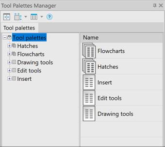
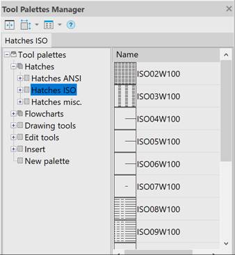
When working with tools, palettes, and groups simultaneously, it is recommended to use both tree and list views. Then, in the right part of the window, you will see the child elements for the node that is selected in the tree on the left side. Double-clicking the icon on the right side of the Tool Palette bar displays the contents of the corresponding folder or tool palette.
.
The group node  has a context menu with the following items:
· Create group – creates subgroup;
· Rename – renames group;
· Move up — moves group position up;
· Move down — moves group position down;
· Remove – removes selected group.
To create a new tool in the Tool Palettes Manager, select an object of the required type in the drawing or in the file explorer and by drag&drop method drag it to the tool palette icon . As a result of this operation, a tool icon will appear in the tool palette with some initial property values (copied from the parent object).
One more method to create a tool is to drag the command from the Tool Palettes Customize Manager window (the window opens by Customize commands... item of the context menu of the tool palette being edited or by TOOLPALETTESCUSTOMIZEMANAGER command) to the palette icon in the tree of the Tool Palettes Manager or to the window of earlier created tools of the palette.
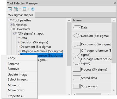
Tool has the following context menu:
· Copy – copies tool to the clipboard;
· Rename – renames tool;
· Remove – deletes tool;
· Select image… – opens Open dialog to select image for tool icon(extensions .jpg, .jpeg, .tiff, .tif, .bmp, .png are allowed);
· Move up — moves tool one position up;
· Move down — moves tool one position down;
· Properties... – opens theTool Properties dialog box.
The Properties... item opens the Tool Properties dialog box with the current settings of the tool and the properties of the objects it creates.
For most objects, the properties window looks like this:
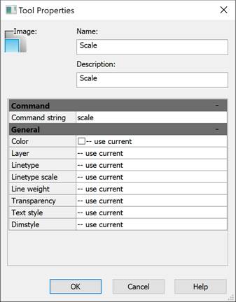
Set necessary properties of selected tool in the General section. Type necessary command options in the Command string fieldCall Select image… context menu to change the icon for a tool. Tool properties dialog looks different for block:
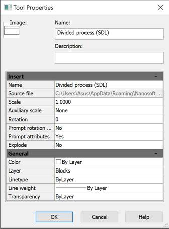
This tool creates a block insertion in the drawing. The General section contains general properties (color, layer, linetype, lineweight and transparency.
Insert section contains specific parameters of the block insertion:
· Name – block name;
· Source file — path and name of the file with block definition;
· Scale – value of insertion scale;
· Auxiliary scale — auxiliary scale factor for block insertion:
· Dimscale – the DIMSCALE system variable value used as an auxiliary scale factor;
· Plot scale – auxiliary scale factor is taken from the plot scale assigned to the current layout of the drawing;
· None – no auxiliary scale factor is used;
· Rotation – rotation angle of the block, used when the Prompt rotation angle is off;
· Prompt rotation angle — turn on/off prompt of rotation angle when block inserted;
· Explode –exploding flag for block insertion (No or Yes).
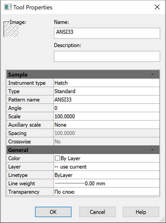
The hatch tool properties dialog box contains options that are specific to hatching:
Use double-click on the tool or drag it into the drawing space. This action calls nanoCAD command with specifyed properties (color, layer, linetype, etc.). If the command has several work options then only the most popular one is chosen. For example, Circle tool calls circle by center and radius.
The block tool also can be executed by double-click or by drag. If auxiliary scale is set in the block tool properties then the final scale for block insertion will be calculated as multiplication of the main and auxiliary scales. If Prompt rotation angle is set to Yes then rotation angle will not be taken from the Rotation parameter and will be requested in command line.
Use Remove item from the tool context menu.
Use Properties... item of the tool context menu to edit parameters of tool.
It is possible to transfer tool palette to another computer. Use Export item of context menu, palette is imported to .xtp file (for further import on a target computer).
This method provides distribution of tools with similar layers, styles settings and other properties to any number of computers engaged in the same project and using nanoCAD.
It is possible to import tool palettes from .xtp files created in nanoCAD or AutoCAD. Use the Import palette item of the context menu in the Tool Palettes Manager.
The current version of nanoCAD does not support AutoCAD multicommand tools (a group of commands can be united under one icon with pop-up menu). nanoCAD displays the following message:
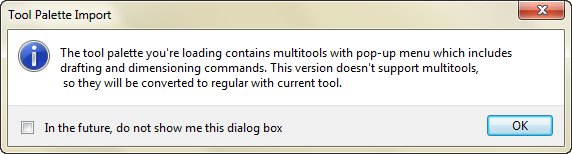
In this case only the last used command of tool is imported instead of the commands group. Command line shows the following messages:
Multitool "Circle by Center and Radius" has been converted to regular.
Multitool "PolyLine" has been converted to regular.
Multitool "Spline" has been converted to regular.
Some tools are unsupported:
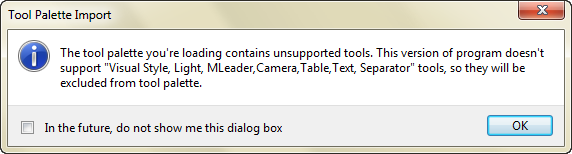
In this case only supported tools are imported. Command line shows the following messages:
Skipped unsupported tool: Light
Skipped unsupported tool: Separator
Skipped unsupported tool: Camera