

 De
De  Es
Es  Fr
Fr  Pt
Pt 

-
-
-
-
-
-
-
-
-
-
-
Coordinate Systems
-
-
-
-
-
-
-
-
-
-
-
-
-
-
-
-
-
-
-
-
-
-
-
-
-
-
-
-
-
-
-
-
-
-
Coordinate Systems
The position of every drawing point is defined by its coordinates. In the command prompt for a point position you can specify it on the screen or type the coordinates in the command line.
Coordinates can be specified in the Cartesian coordinate system and Polar coordinate system.
Cartesian and Polar coordinates can be relative and absolute.
Cartesian coordinate system is defined by three perpendicular axes: X, Y and Z.
The origin of the coordinate system is the point of intersection of the three axes and has the coordinates: (0,0,0).
If you work in the plane, the Z coordinate is always 0, you have to specify X and Y. The X value is specified horizontally and Y value vertically. Positive coordinates are set to the right and above the origin, and negative to the left and below.
When working in three dimensions, you have to set the Z coordinates. By default, the Z axis is set perpendicular to the XY plane from the viewpoint of the observer. The positive coordinates are set above the plane and negative below.
For example, the coordinates (30,20) specify the point set 30 units in on the X axis and 20 units in on the Y axis.
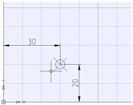
Absolute coordinates are specified from the origin of the coordinate system. Absolute are used if the precise X and Y coordinates are known values.
Example:
The point with coordinates X=10 and Y=20 is the start and the point with coordinates X=30, Y=40 is the end of the line. To create the line, enter in the command line:
|
Command: |
Line |
|
Specify first point: |
10,20 |
|
Specify next point: |
30,40 |
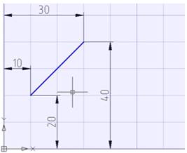
Relative coordinates are used when the distance from the previous point is a known value.
To specify relative coordinates, enter the @ symbol before their values. Values specified after the @ symbol are distances along the X and Y axes from the previous point.
To create a line from the previous example using the relative coordinates enter in the command line:
|
Command: |
LINE |
|
Specify first point: |
10,20 |
|
Specify next point: |
@20,20 |
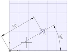
In the Polar coordinate system, the absolute coordinates of a point are set by the distance from the origin and an angle between the polar axis and a line lying through the point and origin. The angle is set in degrees counter clockwise.
For example, the coordinates 40<30 specify a point on the plane, setting the distance as 40 units from the origin and with a 30 degrees angle from the X axis.
Example: The start point of the line is set as 20 units from the origin and at a 45 degree angle from the X axis; the end point is set as 50 units from the origin and 30 degrees from the X axis. Enter in the command line:
|
Command: |
LINE |
|
Specify first point: |
20<45 |
|
Specify next point: |
50<30 |
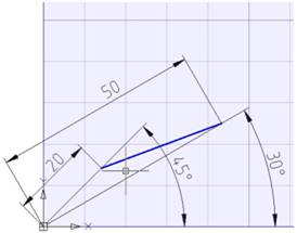
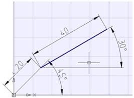
In the relative polar coordinates the distance to the point is set not from the origin, but from the previous point. The angle is specified from the polar axis to the line connecting the previous point and the defining point.
The @ symbol is used to specify relative coordinates.
Example:
The start point of a line is set as 20 units from the origin and at a 45 degree angle from the X axis; the end point is set as 40 units from the previous point and 30 degrees from the polar axis. Enter in the command line:
|
Command: |
Line |
||
|
Specify first point: |
20<45 |
|
|
|
Specify next point: |
@40<30 |
|
|
Specifying Points With “Direction – Distance”
The direct distance is set instead of entering coordinates; it is very useful for quickly entering the lengths of lines.
Using direct distance specifying, move the cursor in the desired direction and enter the length value in the command line at the command prompt: Specify next point:. If ortho mode is switched on, it is very useful for drawing perpendicular lines.
This method can be used in all commands, except commands where just a value is needed, for example Array,Divide etc.
Coordinate filters are entered in response to a point request and define the axes along which coordinates will be set. You can enter the following filters: .x, .y, .z, .xy, .xz or .yz.
Coordinate filters allow you to input the coordinates of a point for each axis separately, specifying coordinates first along one axis, then along another.
Coordinate filters are useful when the value along one axis is determined by one characteristic point of the object, and along the other axis by another point. When using coordinate filters, it is possible to extract one coordinate value at a time from selected characteristic point of an object by using a snap.
For example, you need to enter the coordinates of a point, located in the center of a drawn rectangular window.
In response to a point request:
Specify point:
1. Enter filter: .x
The request will change its appearance. Now not all coordinates are requested, but only the value along the X axis:
Specify point: >> X
2. With the Midpoint snap activated, specify the horizontal edge of the window. This will define the coordinate of the point along the X axis.
Now the coordinates for the remaining Y and Z axes are requested:
Specify point: >> YZ
3. We are satisfied with the mode of cleaving coordinates from a point simultaneously along two specified axes. Therefore, it is not necessary to enter any other coordinate filters. With the Midpoint snap activated, select the vertical edge of the window. This will define the coordinates of the point along the Z and Y axes.