


 De
De  Es
Es  Fr
Fr 

-
-
-
-
-
-
-
-
-
-
-
-
-
-
-
-
-
-
-
-
-
-
-
-
-
-
-
-
-
-
-
-
-
-
-
Create TIN by Points
-
-
-
-
-
-
-
-
-
-
-
-
-
-
-
-
Create TIN by Points
 Ribbon: Topoplan – Create TIN >
  Create TIN by Points
Menu: Topoplan – Create TIN >  Create TIN by Points
Toolbar: Create TIN > Create TIN by Points
 Command line: NG_CREATE_TIN
The command creates a TIN (Triangular Irregular Network) surface – an irregular triangulation network by point objects represented by Points, Geopoints or Blocks. The following objects can be created: SubMesh, Polyface mesh, Solids or 3D Faces.
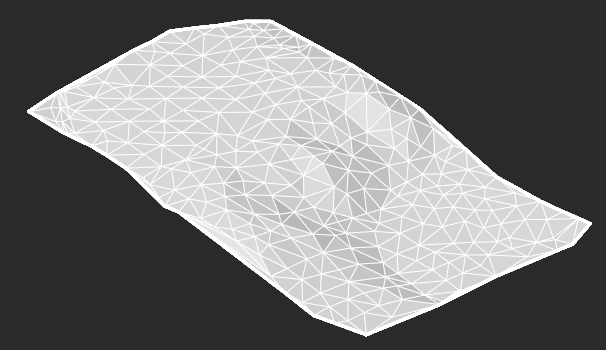
A set of points for creating a mesh can be obtained by importing from third-party formats or from a point cloud with the Explode the Cloud into Points command.
The command options are set on the Properties bar.
Options:
|
Result type values |
PolyFace mesh – creates an object of Polyface mesh type, the nodes of which can be edited; SubMesh – creates an object of SubMesh type without the ability to edit nodes; Solids – will create a triangulation model consisting of separate triangle objects of Solid type; Faces – will create a triangulation model consisting of separate triangle objects of 3D Face type. |
|
Filtrate source points |
You can change the number of points that will be used to build create triangulation. To do this, select Yes for the Filtrate source point option, select the type of filtration for Filter Units parameters and set the desired value in the Filter range field. This will create a mesh with fewer number of larger triangles. This accelerates the process of creating a triangulation model. The created model will be less accurate, but its further processing will take less time. The following filtration types are possible: · Points number – the number of points to be used to create a triangulation model. The total number of points can be determined by selectin all objects of Point (or Geopoint, Block) type by which triangulation will be created. · Percent of points number – the percent of points that will be used to create a triangulation model. It is convenient to use when you know the minimum percentage of points that allows you to build a mesh of acceptable quality; · Maximum error – the maximum distance in drawing units from the surface formed by the bulk of points, beyond which points will be excluded from triangulation. It is convenient to use for creating a triangulation mesh over the earth's surface, automatically filtering out other objects: noises, trees, constructions, etc. |
|
Build boundary from convex hull |
When this option is enabled, after creating the triangulation the mesh will be processed. Triangles with an edge length greater than the specified one will be removed. The length value is specified in the Max edge field. The length is specified as a percentage of the maximum edge units of the face in a triangulation model or in drawing units (based on the value of Max edge units parameters). |
|
Max edge units |
The length units for the Max edge parameter. Percentage of the units of the maximum face edge in the triangulation model or drawing units (set in the UNITS dialog). |
|
Max edge |
The maximum allowed edge length. All triangles with edges longer than this value will be removed from triangulation. A value of zero disables filtering by edge length. The length is specified as a percentage of the max edge units of the face in the triangulation model or in drawing units (based on the value of the Max edge unit). |
|
Min triangle angle |
The minimum angle in the triangle at which it will not be filtered. A zero value disables filtering by angle value. Triangles are filtered by plan angles, as other filtering options also operate plan length values.. This parameter allows you to exclude extended triangles from triangulation. The value is specified in drawing angular units. If the drawing units are set to Degrees-minutes-seconds or Topographic units, the parameter value is measured in degrees. |
|
Min. triangles |
The number of triangles that will be removed. When contouring, many small islands are created from several triangles. Islands with fewer triangles than the specified parameter will be removed. |
|
Only external boundary |
This option allows you to apply filtering not to the entire network, but only to triangles on its outer boundary. When this option is enabled, only triangles located on and adjacent to the boundary of the network will be removed during mesh processing Filtering only on the boundary can be useful when, as a result of triangulation, the distant vertices of the mesh boundary are connected by edges, forming parasitic super elongated narrow triangles.
|
|
Project points to UCS XY plane |
When this option is enabled, the triangulation will be created in the XY plane of the user coordinate system. When the option is disabled, the triangulation will be created in the plane of the current view. |
|
Select region |
It is used when you need to build a model not by all points, but only by a certain part. In this case, click the button to the right of the Region is not selected value and draw a polygonal area within which the triangulation will be created on the point cloud. |
|
Generate normals |
Shading parameter. Calculates normals at the mesh vertices, resulting in a smoother mesh appearance in the Precise view. The option is available only if a mesh is selected as the resulting triangulation object.
|
|
Generate per vertex colors |
Colors the faces and vertices of the mesh according to the points color. The option is available only if a mesh is selected as the resulting triangulation object.
|
|
Break for optimization |
If the triangulation model turns out to be very detailed (millions of faces), then for the possibility of further convenient work, it will be divided into several meshes. If the parameter is disabled, the model will not be split, a single mesh will be created. |
|
Filter by layer |
The possibility to create a surface only by objects of a certain layer. When you select Yes in the drop-down list, it is necessary to specify the layer. |
|
Create layer |
When you select Yes, the mesh will be created on a new layer TIN surface. |
|
Use Z coordinate from |
The option is available if the TIN is based on geopoints. Specifies where to take the coordinate of the TIN vertices along the Z axis. Allows you to take the value from the point elevation (z-coordinate) or any custom attribute of the geopoint of the corresponding format, if any. A custom parameter appears in the replacement list only if all selected geopoints have a numeric value for this parameter. |

Command prompts:
|
Apply changes? <Yes> or [Yes/No]: |
Yes – the command will be performed taking into account changes in settings made by the user in the current command session. . No – the command will be performed with the settings that displayed right after the command started. Save – saving settings to the document. saveDefault – saving settings to the register. |