
 De
De 

-
-
-
-
-
-
-
-
-
-
-
-
-
-
-
-
-
-
-
-
-
-
-
-
-
-
-
-
-
-
-
-
Chain Note
-
-
-
-
-
-
-
-
-
-
-
-
-
-
-
-
-
-
-
-
-
-
Chain Note
 Ribbon: Home, Annotate – Leaders >
  Chain note
 Menu: Draw – Notes >
  Chain notes…
Toolbar: Utilities –
 Command line: NOTEH
The command opens the Chain note dialog box to set the note options:
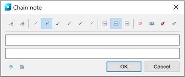
Options:
|
|
Managing multiline text output above the leader. |
|
|
Framing the text under the leader. |


Use the icons to select the style of the extension line:
|
|
None. |
|
|
Arrow. |
|
|
Point. |
|
|
Open arrow. |
|
|
Half-arrow. |
|
|
Oblique. |


Use the icons to select the text alignment method:
|
|
By left edge. |
|
|
By center. |
|
|
By right edge. |


Other icons:
|
|
The Insert special symbol icon opens the panel with the table of special symbols, to select and insert them at the current cursor position in the text input field. |
|
|
The Notepad icon opens the Notepad dialog box. |
|
|
The Match properties icon temporarily closes the dialog box to specify the inserted leader whose properties should be copied and applied to the newly-created leader. |
|
|
The Add extension line icon is used to insert additional extension lines. The icon is available when you edit a chain note inserted into the drawing. |


Right-click in the text field and choose the required menu item:
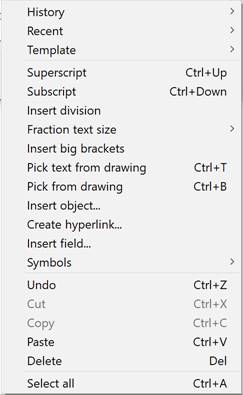
For more information about additional commands, see the Mechanical Note section.
To create a chain note:
1. Type the required text into the text fields.
2. Select the required note options.
3. Click OK.
4. Specify the first leader node.
5. Specify the next leader nodes.
6. Specify the last node and press ENTER.
7. Specify the shelf position.
If the first leader node is placed on the line, the extension line will be perpendicular to this line.