
 De
De  Es
Es  Fr
Fr 

-
-
-
-
-
-
-
-
-
-
-
-
-
-
-
-
-
-
-
-
-
-
-
-
-
-
-
-
-
-
-
-
-
-
-
Geopoint Object
-
-
-
-
-
-
-
-
-
-
-
-
-
-
-
-
-
Geopoint Object
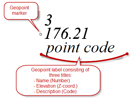
Geopoint is a coordinate geometry oriented (COGO) point, which, in addition to coordinates can contain additional attributes and store styles for displaying labels and markers.
In nanoCAD a geopoint is represented as a separate object. A geopoint and a simple point are different objects: a classic nanoCAD point contains only coordinates.
Geopoints can be imported in the document by the Import Geopoints command.
Geopoints can be created manually by the Create GeopointsManually command or obtained as a result of the work of the Explode the Cloud into Points command.
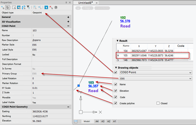
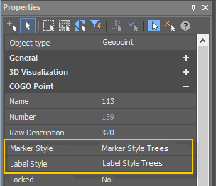
The properties of a geopoint, like any other objects, can be edited in the Properties bar.
Geopoints have grips, the movement of which is initiated by: moving a geopoint, rotating a marker, moving and rotating a label. The same parameters can be changed in the Properties bar:
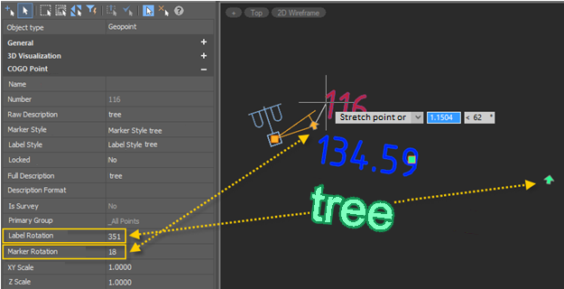
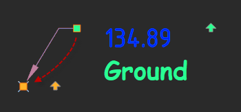
The grip for moving the label allows you to expand the geopoint’s label and marker with the formation of a leader with an arrow. To return the label to its previous position, just drag the grip for moving the label onto the grip for moving the geopoint.
It is possible to snap to geopoints in the Node mode.
It is possible to change the scale of geopoints. To do this, use the commands - Toposcale 1:500, Toposcale 1:1000, Toposcale 1:2000, Toposcale 1:5000. When executing the Toposcale command, the presence of geopoints and an ultrasonic classifier in the drawing is checked. If they exist, it is proposed to rescale them.
The following changes are made for geopoints:
- marker sizes in all geopoint marker styles,
- label sizes in all geopoint signature styles.
Geopoints in the Drawing Explorer
|
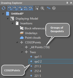
To organize points and control how they are displayed in a drawing, ou use collections of named points called point groups. Geopoints are displayed in the Drawing explorer, each in its own group. The same bar displays sets of geopoint marker styles, geopoint label styles, custom properties of geopoints. |
|
Marker and Label Styles of Geopoints
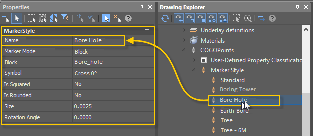
The marker styles and label styles of geopoints are used to change the display of a geopoint in the drawing field.
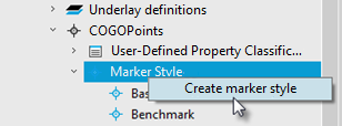
You can create new marker styles and label styles of geopoints from the context menu of Drawing Settings - COGOPoints - Marker Style or Label Style in the Drawing Explorer.
Editing geopoint marker styles is started by double-clicking on the desired marker style in the Drawing Explorer. Parameters are configured in the Properties bar.
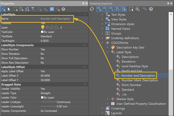
Editing geopoint label styles is started by double-clicking the desired label style in the Drawing Explorer. Parameters are configured in the Properties bar.
To organize points and control how they are displayed in a drawing, use collections of named points called point groups.
Groups of geopoints can be created by the Create a Group of Geopoints Manually and Create Groups of Geopoints by Original Description commands.
Double clicking on the name of a group of geopoints in the Drawing Explorer starts editing the parameters of the group in the Properties bar:
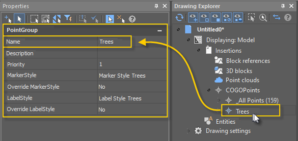
A group can be assigned with a geopoint marker style and a geopoint label style. When style override is enabled, the group style will be applied to all geopoints in that group. After disabling the style override, the appearance of the marker or label of each point in the group will return to the view specified in the point.
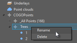
You can rename or delete a group of points using the commands of named group context menu in the Drawing Explorer.
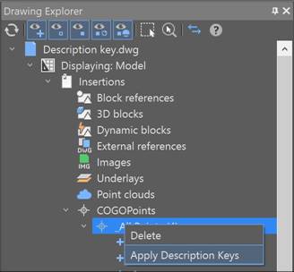
A Description key sets can be applied to a group of geopoints. The command is applied to a group in the drawing explorer using the context menu. More information about description keys in the section Description Key Sets.
User-Defined Properties of Geopoints
You can set user-defined properties for geopoints. If you have additional data that cannot be distributed over existing standard geopoint properties, you can specify your own user-defined properties.
There are four types of user-defined properties available:
· String: allows you to enter text as a value. Is used when you want to enter any alphabetic or numeric characters.
· Integer: allows you to enter only whole numbers without decimals.
· Double: creates a property that allows you to enter numbers with decimal places.
· Boolean: creates a property that allows switching Yes/No (true or false) value.
|
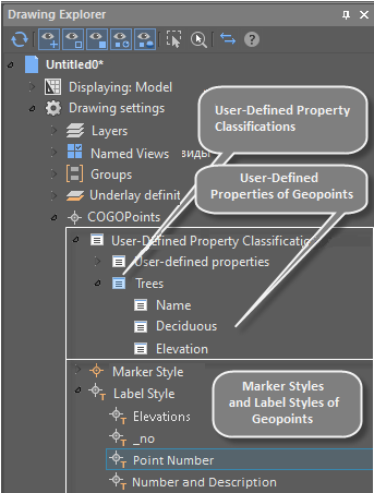
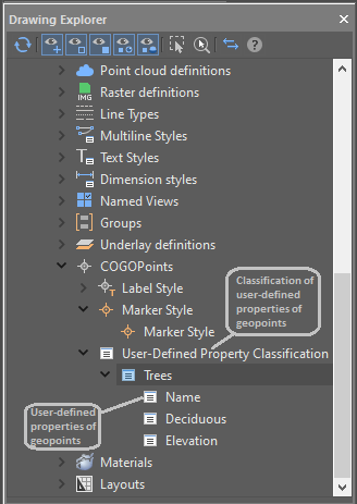
Geopoint user-defined properties are grouped into user-defined property classification. A classification can be created, filled with user-defined properties, or deleted. Thus, if you have a survey that contains tree data, you can create a Trees classification. Then create user-defined properties in it related to this classification. For example: · Name (String), · Deciduous (Boolean), · Elevation (Double).
All user-defined properties of geopoints and their classifications are displayd in the Drawing Explorer (Drawing settings – COGO-points – User-defined Property Classification). |
|
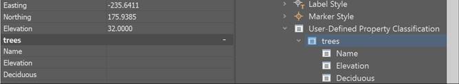
You can view and edit the values of user-defined geopoint properties of the drawing in the Properties bar.
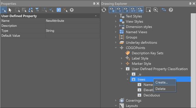
You can create a new user-defined property classification by selecting Create in the context menu of the Drawing settings – COGO Points – User-defined Property Classification section in the Drawing Explorer.
You can create a new custom property by selecting Create in the context menu of any user-defined property classification in the Drawing Explorer.
You can set a description for a custom property. The use of descriptions will be implemented in one of the next versions.
User-defined properties can also be assigned during the import of geopoints by the Importgeopoints command.
You can delete a classification or a user-defined property by selecting Delete in their own context menu in the Drawing Explorer.