
 De
De 

-
-
-
-
-
-
-
-
-
-
-
-
-
-
-
-
-
-
-
-
-
-
-
-
-
-
-
-
-
-
-
-
-
-
-
-
Add Structure Line
-
-
-
-
-
-
-
-
-
-
-
-
-
-
Add Structure Line
 Ribbon: Topoplan – Modify TIN >
  Add Structure Line
Menu: Topoplan – Editing TIN >  Add Structure Line
Toolbar: Editing TIN > Add Structure Line
 Command line: NG_MESH_STRUCTURAL_CREATE
The command adds a new structure line or a retaining wall to the existing surface.
Structure lines are used to detail relief forms. Such lines can describe lines of curbs, pavement boundaries, gulleys, watersheds, etc. When there are structure lines present, the surface triangulation is forced along the structure line; triangulation edges cannot intersect a structure line. Types of objects that can be added as structure lines: lines, polylines, 3D polylines.
The command supports multiple selection.
The command options are set in the Properties bar.
Options:
|
Structural type |
Type of structure line: Standard or Retaining wall. |
|
Project profile on |
The parameter is used for the standard structure line. · WCS – the polyline will be projected onto the XY plane of the world coordinate system; · UCS – the polyline will be projected onto the XY plane of the custom SC; · Viewport – the polyline will be projected onto the viewport plane. |
|
Get Elevation from |
The parameter is used for the retaining wall. Specify the source of marks: · Structural Line – marks will be taken from the line specified when drawing. To obtain a polyline with surface elevations, you can use the Draw structure line or Project line to mesh. · Surface – the command will project a line onto a surface and take marks from the surface. |
|
Set Wall Height |
A method to specify the height of the retaining wall: · Separately – during construction, the height of the wall for each vertex of the line will be requested. · Common – constant height, defined by the Common Wall Height parameter. |
|
Common Wall Height |
Uniform wall height for the case when the Set Wall Height – Common. The height can be positive or negative. |
|
Type of work (for closed contours) |
The parameter is available if a closed polyline is selected: · Saving internal points – surface points that fall inside the closed line will be saved. · Removing internal points – surface points that fall inside the closed line will be removed, and the surface will be rebuilt.
|
To add a structure line:
1. Run the command.
2. Set the parameters in the Properties bar. The Structural type should have the Standard value. Press ENTER in response to the prompt in the command line:
Apply changes? <Yes> or [Yes/No]:
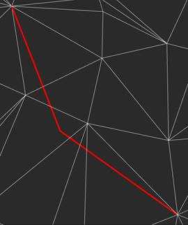
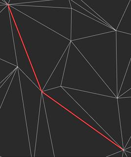
3. In response to the prompt
Select polyline or line to be added as structural line or [?]:
specify a line, polyline or 3d polyline. After selecting an object by the cursor, triangulation will be rebuilt.
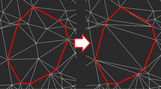
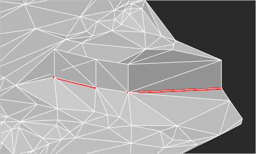
|
Surface before adding a structure line |
Surface after adding a structure line |
|
|
|
To add a Retaining wall structure line:
Run the command.
Configure the parameters in the Properties bar. The Structure type should have the Retaining will value. Press ENTER in response to the prompt in the command line:
Apply changes? <Yes> or [Yes/No]:
In response to the prompt
Select polyline or line to be added as a structural line or [?]:
specify a line, polyline or 3d polyline.
In response to the prompt
Specify the side of the wall offset:
specify the slope side.
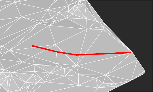
If the Set the wall height parameter was set to Separate vertices, then specify the wall height for each line vertex. The current vertex is indicated by a red circle.
The mesh triangulation will be rebuilt. The retaining wall is always vertical in the World coordinate system.
The command supports multiple selection.