
 De
De 

-
-
-
-
-
-
-
-
-
-
-
-
-
-
-
-
-
-
-
-
-
-
-
-
-
-
-
-
-
-
-
-
-
-
-
-
-
-
-
Measurement Archive
-
-
-
-
-
-
-
-
-
-
-
Measurement Archive
The work with measurements can be divided into 2 stages: collection of a measurement files archive and formation of a project underlays collection from this archive.
An archive of measurement files contains raw or preprocessed data, while a set of prepared underlays should be groups of geopoints ready for use in projects.
Filling the archive of measurement files
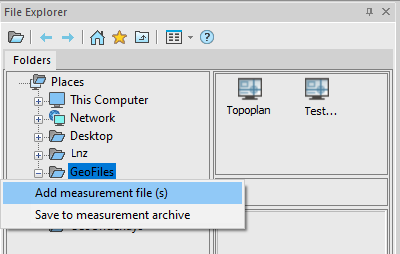
Measurement files are stored in the Geofiles folder. The path to the folder is defined in the Standard directories section of the Options dialog.
To add a file to the archive, the  Add measurements command is used, with the help of which the required file on the disk is specified, if necessary, a new name is given to it, after which it is copied to the measurement archive.
If you need not only to save a raw file, but to carry out a full import at this stage, so as not to return to setting parameters later, then you should use the  Save to the measurement archive command. You need to configure the parameters in it, after which the result in the form of a DWG file is placed in the archive.
The measurement archive is displayed in the file explorer in Geofiles folder. By expanding it, you can view all archive measurement files.
Creating selections and forming a set of underlays
To work with points, it is necessary to form selections from the measurement archive.
Selections are formed by special commands in the form of separate DWG files, which are subsequently placed as external references in working drawings. Thus, the same selection (underlay) can be inserted into several different working DWG files.
To form a selection:
1. Create a new underlay with the  Insert a Geounderlay command.
2. Import the required measurements into it from the archive using the  Importmeasurements command
3. Configure groups of points, forming them, if necessary, and setting their parameters (styles). Enable/disable the visibility of the desired groups.
4. Save the drawing to the collection of underlays as a separate named entity using the  Save as geounderlay command.
The underlay collection is a separate Geofiles folder. The path to the folder is defined in the Standard directories section of the Options dialog.
It is also visible in the File Explorer as the Geofiles folder. By expanding it, you can view all the underlay files.