
 De
De  Es
Es  Fr
Fr 

-
-
-
-
-
-
-
-
-
-
-
-
-
-
-
-
-
-
-
-
-
-
-
-
-
-
-
-
-
-
-
-
-
-
-
-
-
-
-
-
-
-
-
-
-
-
Import Geopoints
-
-
-
-
-
-
-
Import Geopoints
 Ribbon: Topoplan – Import/Export >
  Import geo-points
Menu: Ground – Import/Export >  Import Geo Points
Toolbar: Import/Export > Import Geo Points
 Command line: NG_IMPORT_POINTS
The command is designed to import text files from CSV, SDR (Sokkia), XYZ and TXT. In the import dialog you can configure the rules for interpreting and uploading file contents.
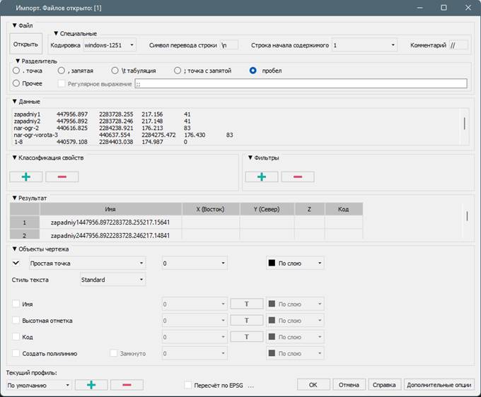
Options:
|
Open |
Open text file CSV, SDR (Sokkia), XYZ and TXT to import geodata. You can open multiple files at the same time. |
|
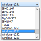
Encoding |
Encoding of the imported text file.
|
|
New line character |
Allows you to override the newline character. The default character is \n. |
|
Content start line |
Line number of significant content, if the file beginning contains any service information, except for point coordinates. |
|
Comment |
Specifies the character that is used to comment lines. Commented lines are not considered as data during import. If there are no comments in the file, then leave the field blank. The default character is \\. |
|
Separator |
Specifies a character that separates data in a text file. You can choose both predefined ones (period, comma, semicolon, tab character, space), or set any other, if necessary, using regular expressions. |
|
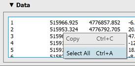
Raw data |
Preview of text file data. Selected data can be copied.
|
|
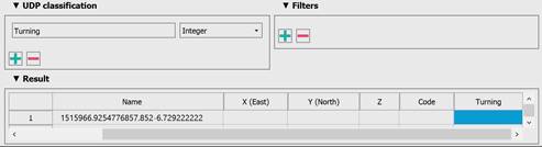
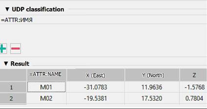
UPD classification |
You can add custom properties to points with the
A new empty column with the name of the custom parameter appears in the Result table. Drag this column heading onto the heading of the column you want it to match.
You can delete unnecessary custom properties with the Upon the points are imported, custom properties can be viewed and edited in the Properties bar just like other properties.
If the table has more than 5 columns, then a new column is not created, but the name of the 6th is overwritten.
|
|
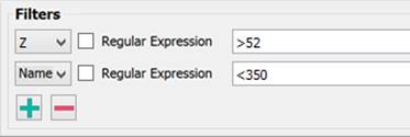
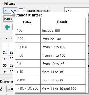
Filters |
You can exclude data from import not only manually by deleting cells from the Result table, but also by setting filters. For example, you can exclude from import all points with heights below 52 (column Z) and with a number greater than 350 (column Name).
After adding the filter with the
It is recommended to set filters only after correct data typing in the Result section. |
|
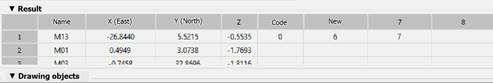
Result |
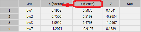
The table specifies the correspondence of the text file columns to certain data types: point X, Y and Z coordinates, numbers, point descriptions. The column heading displays the data type. In case of incorrect initial data typing, you can drag one column to another by the header, mutually changing the data in these columns.
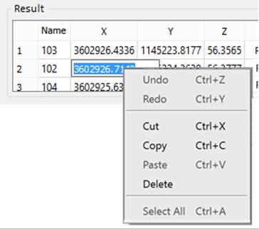
You can delete selected cells, rows, or columns. Multiple selection is supported using SHIFT and CTRL. Rows or columns are selected by clicking on the heading. Before manually deleting data, it is recommended to filter it out using filters. You can also edit the data after double-clicking on a cell.
|
|
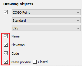
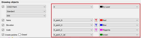
Drawing objects |
The section determines the form objects the geopoints should be imported from an external file (that is, by what objects they will be represented in the drawing). And also what titles the point label will consist of, and what design they will have.
You can import geodata as: · Common Point objects with labels as text objects; · Blocks (like blocks from the Conventional sign bar) · Objects of the Geopoint type with a label.
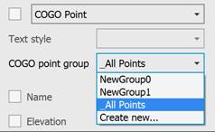
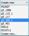
In case of importing data in the form of COGOpoint object, specify a group for them in the drop-down list below.
The list contains only groups of geopoints that exist in the current drawing. To create a new group, select the Create new option and enter a name for the new group.
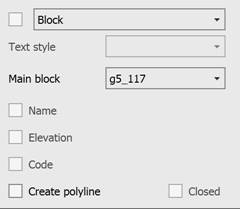
If the Block was selected, the imported points will be presented as block inserts with single-line attributes to display label titles. To do this, a new block will be created in the drawing. The conventional sign for the point marker will be taken from the block in the dropdown list below.
Only the blocks that already exist in the current drawing are available in the list. To make the blocks of the Conventional signs toolbar available, insert at least one conventional sign into the drawing. When importing, it is possible to select a block for the marker and the main block (marker + attributes). If the main block existing in the drawing is selected, you can add block attributes in the property classification (they will appear as columns in the table for further editing). The block selected for import is analyzed for the presence of attributes. Next, select an attribute that, when imported, will be filled with data from the point file. When adding an attribute, one of the existing parameters should be selected from the proposed ones (attribute, udp, rotation); if a new attribute is created, then the "=" sign should not be there. |
|
|
The blocks will be inserted with a scale that takes into account the values of the current topographic scale. If the Create new option is selected instead of selecting an existing block in the list, then after starting import, the block editor will open to create a point marker (conventional sign) block. The default is a circle. In the block editor, edit the marker, save the block, and exit the editor to complete the import. When choosing to import a block from the list of those existing in the drawing, the selection of such attributes as Name, Elevation, Code is irrelevant – they will not be created additionally. They are grayed out and blocked.
|
|
|
You can mark which attributes will be displayed in the geopoint description on the drawing: geopoint number (name), elevation (Z-coordinate) and code (point description).
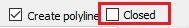
You can automatically create a polyline connecting all imported points. For example, if these are points of a road or a building.
To place points and titles, you can assign individual layers and colors. Titles can also be assign with a font.
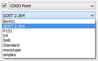
Labels can be assigned to a style.
|
|
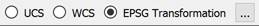
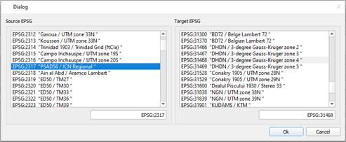
Recalculate by EPSG |
Select in what coordinate system to import geodata: World or Custom ones or recalculate by EPSG codes:
|
|
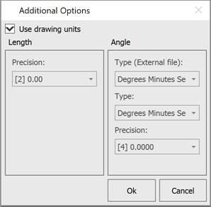
Additional Options |
The Additional Options button opens the window where you can change the settings for the units (UNITS) with which geopoints should be imported. By default, the current drawing units are used. The Type (External file) setting allows the user to set the data format in the external file. The data is converted into a format that is more convenient to edit and transferred to the drawing.
|
|
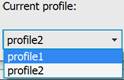
Current profile |
Allows you to save all the settings made in the dialog to a profile for further use.
|
 button. You should specify the type (integer, float, or string) and name.
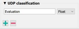
 button.
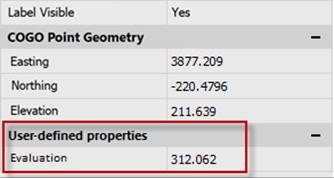
When Importing geopoints, standard styles are created.
You can change the standard style by starting editing it from the Drawing Explorer.
note Files larger than 10000 lines are not supported. To be able to work with the data, split the file into smaller parts.