
 De
De 

-
-
-
-
-
-
-
-
-
-
-
-
-
-
-
-
-
-
-
-
Spline
-
-
-
-
-
-
-
-
-
-
-
-
-
-
-
-
-
-
-
-
-
-
-
-
-
-
Spline
 Menu: Draw –
  Spline
Toolbar: Draw –
 Command line: SPL, SPLINE
A spline is a smooth curve passing through a given set of points. Example of spline usage: line breaks of objects.
Spline can be created by two methods:
Fit points
|
|
When creating splines using fit points, the resulting curve goes through the specified points and depends on intervals between mathematic knots of curve. |
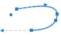
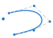
Control vertices
|
|
When creating splines using control vertices, temporary lines are displayed between the specified points, they form control polygon that defines the spline form. |
Command options:
|
Method |
Selects the method of creation [Fit/Control] |
|
Object |
Converts a polyline, smoothed by the Spline and Smooth commands, to an equivalent spline. |
|
Close |
Closes a spline. |
|
Fit tolerance |
The maximum distance from a spline curve to any points defining it. |
|
Undo |
Successively reverses the specified points. It is impossible to undo the specified start point. |
Creating Splines by Fit Points Method
Ribbon: Main – Draw >  Fit points
Menu: Draw – Spline > Fit points
 Toolbar: Draw – Fit points
Command line: SPL, SPLINE – Method > Fit
Command prompts:
|
Current settings: Method=Fit |
|
|
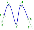
Specify first point or [Method/Object]: |
Specify a start point 1. |
|
Specify second point: |
Specify second point 2. |
|
Specify next point [Fit tolerance/Undo] <start tangent> |
Specify 3, 4, 5 etc. points. |
|
Specify next point or [Close/Fit tolerance/Undo] <start tangent> |
Press ENTER to finish specifying points. |
|
Specify start tangent: |
Specify a tangent 6 for the start spline point. |
|
Specify end tangent: |
Specify a tangent 7 for the end spline point. |
Creating Splines by Control Vertices Method
Ribbon: Main – Draw >  Control vertices
Manu: Draw – Spline > Control vertices
Toolbar: Draw – Control vertices
Command line: SPL, SPLINE – Method > Control
Command prompts:
|
Current settings: Method=Cv |
|
|
Specify first point or [Method/Object]: |
Specify the spline start point. |
|
Specify second point: |
Specify the second point. |
|
Specify next point or [Undo]: |
Specify the next point. |
|
Specify next point or [Close/Undo]: |
Specify all next points. Press ENTER to close the command. |
Lines, polylines, spline-smoothed polylines, arcs, circles, elliptical arcs can be transformed into a spline.
|
Specify first point or [Method/Object]: Object |
Select the Object option. |
|
Select objects to convert to splines or [?]: |
Select objects. |
|
|
Press ENTER to complete the command. |