Help Center

EDITING

CAD drafting EDITING 0Main menu: Mechanical - Edit - CAD software EDITING 1Edit....

CAD drawing EDITING 2Ribbon: Mechanical - Utilities - CAD drafting EDITING 3Edit....

CAD software EDITING 4Toolbar: CAD drawing EDITING 5Edit... ( "Edit").

CAD drafting EDITING 6Context menu: Edit (on select object).

CAD software EDITING 7Command line: MCEDIT, EDIT.

Editing Building Ground23 - objects can be made in the following ways:

      ·    right-clicking and selecting Edit Edit from the context menu;

      ·    double-clicking the left mouse button on the nanoCAD Mechanica23 - object. This method is specified in the settings;

      ·    with "grips";

      ·    calling on the Edit tooltip that appears when you hover the cursor over an object:

CAD drawing EDITING 8

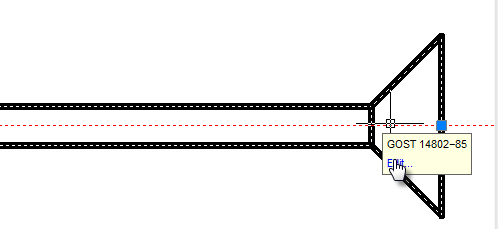
      ·    properties dialog box (properties);

      ·    standard commands Erase (ERASE), Move (MOVE), Copy (COPY), Rotate (ROTATE), Stretch (STRETCH).

Edit in-place

CAD drafting EDITING 9Main menu: Mechanical - Edit - CAD software EDITING 10In-place edit.

CAD drawing EDITING 11Ribbon: Mechanical - Utilities - CAD drafting EDITING 12In-place edit.

CAD software EDITING 13Toolbar: CAD drawing EDITING 14In-place edit ( "Edit").

CAD drafting EDITING 15Command line: MCIPEDIT, IPEDIT.

Command allows you to edit the drawing objects Construction site containing text.

Editing can be done on site by clicking the left mouse button while pressing Ctrl.

CAD software EDITING 16CAD drawing EDITING 17

Group Edit

CAD drafting EDITING 18Main menu: Mechanical - Edit - CAD software EDITING 19Group edit.

CAD drawing EDITING 20Ribbon: Mechanical - Utilities - CAD drafting EDITING 21Group edit.

CAD software EDITING 22Toolbar: CAD drawing EDITING 23Group edit ( "Edit").

CAD drafting EDITING 24Command line: MCEDITGROUPS.

The command allows you to edit bolted  or riveted connections.

      ·    Click on the button CAD software EDITING 25 Group edit;

      ·    Select any item in the drawing either a bolted or riveted joint;

In the window that opens, make the necessary changes.

Furthermore, editing group nanoCAD Mechanica23 - objects can be produced by double-clicking the left mouse button on the axis of the assembly.

Regenerate

CAD drawing EDITING 26Main menu: Mechanical - Edit - CAD drafting EDITING 27Regenerate.

CAD software EDITING 28Ribbon: Mechanical - Utilities - CAD drawing EDITING 29Regenerate.

CAD drafting EDITING 30Toolbar: CAD software EDITING 31Regenerate ( "Edit").

CAD drawing EDITING 32Command line: MCREGEN, REGEN.

      ·    Updates the object's nanoCAD Mechanica

      ·    Recalculates the table

      ·    Updates overlapping objects

      ·    Automatically updates the calculated values of the attributes

Explode all

CAD drafting EDITING 33Main menu: Mechanical - Edit - CAD software EDITING 34Explode all objects.

CAD drawing EDITING 35Ribbon: Mechanical - Utilities - CAD drafting EDITING 36Explode all objects.

CAD software EDITING 37Toolbar: CAD drawing EDITING 38Explode all objects ( "Edit").

CAD drafting EDITING 39Command line: MCEXPLODEALL, EXPLODEPDEALL.

Explodes all objects of nanoCAD Mechanica into drawing primitives.

Explode primitives

CAD software EDITING 40Main menu: Mechanical - Edit - CAD drawing EDITING 41Explode All Primitives.

CAD drafting EDITING 42Ribbon: Mechanical - Utilities - CAD software EDITING 43Explode All Primitives.

CAD drawing EDITING 44Toolbar: Edit - CAD drafting EDITING 45Explode All Primitives.

CAD software EDITING 46Command line: MCEXPLODEPSEUDO, EXPLODEPSEUDO.

Explodes Primitives and Pseudo-Primitives that are generated when nanoCAD graphics are overlapped by objects  nanoCAD Mechanica.

Procedure

1. Call the command.

2. Confirm the layout of the primitives.

3. The primitives will be broken.

Before

After

CAD drawing EDITING 47

CAD drafting EDITING 48

Export drawing file

CAD software EDITING 49Main menu: Mechanical - Edit - CAD drawing EDITING 50Export to file.

CAD drafting EDITING 51Ribbon: Mechanical - Utilities - CAD software EDITING 52Export to file.

CAD drawing EDITING 53Toolbar: CAD drafting EDITING 54Export to file ( "Edit").

CAD software EDITING 55Command line: MCEXPORTTOFILE.

Saves selected objects in the drawing file.

    1.    Click CAD drawing EDITING 56Export to file

    2.    Select the drawing objects

    3.    In the dialog box, type the required settings drawing

    4.    Click OK

    5.    In the dialog box, specify a name for the drawing, and then click Save

Parameters Redefinitions

CAD drafting EDITING 57Main menu: Mechanical - Edit - CAD software EDITING 58Parameters redefinition.

CAD drawing EDITING 59Ribbon: Mechanical - Utilities - CAD drafting EDITING 60Parameters redefinition.

CAD software EDITING 61Toolbar: Edit - CAD drawing EDITING 62Parameters redefinition.

CAD drafting EDITING 63Command line: MCPR, PR.

The basic rules

This command is used to define the variations of the nanoCAD Mechanica design objects settings in the current drawing.nanoCAD Mechanica23 The redefinition is controlled by the parameters set in the setting of design elements.

CAD software EDITING 64

The objects are grouped by types in the dialog. The objects parameters are grouped by name.

To set the parameters or Redefinition removal filter lists are:

CAD drawing EDITING 65

If any type is selected in the parameters table , the parameters list concerning the given type is displayed.

The standard filter list allows specifying different settings for single objects created by a different design standard.

CAD drafting EDITING 66

If you select "All" standards - the changes will be applied to all objects if you select only one of the standards (eg GOST), the changes will only be used for objects belonging to the chosen standard.

Command Options

If an object type is selected, its properties will be displayed in the parameters table.

CAD software EDITING 67

Redefined parameters are shown in blue. To remove the overriding need to press the CAD drawing EDITING 68 opposite setting.

In addition, you can manually specify a new value for the selected parameter. If the new value is the same default, the blue light will not be displayed. If the selected object group only some entries have the override, the backlight will override the diagonal.

CAD drafting EDITING 69

To remove the override all objects need to click on the CAD software EDITING 70 bottom left of the dialog.

Action sequence

To change the settings of one or more design elements, you must:

      ·    Select objects

Next, in the dialog box to specify the new settings data display objects. Changes apply only to the selected objects.

Change the parameters of objects can also be by a separate command CAD drawing EDITING 71 Parameters redefinitions.

Checking the settings of design elements

To verify the design elements specify the settings, you must run the CAD drafting EDITING 72Parameters redefinition. It is proposed to select the objects that will be exposed to the command.

CAD software EDITING 73

When you press the Enter will select all elements of design Construction Site 4. When you press the Enter will select all elements of design Construction Site 4 . Next, press the button Clear redefinition from all parameters

CAD drawing EDITING 74

The result is a document issued in accordance with the settings specified in the enterprise (in terms of elements nanoCAD Mechanica23).

Find and Replace

CAD drafting EDITING 75Main menu: Edit - CAD software EDITING 76Find and Replace....

CAD drawing EDITING 77Main menu: Mechanical - Edit - CAD drafting EDITING 78Find and Replace....

CAD software EDITING 79Ribbon: Mechanical - Utilities - CAD drawing EDITING 80Find and Replace....

CAD drafting EDITING 81Toolbar: Edit - CAD software EDITING 82Find and Replace....

CAD drawing EDITING 83Command line: MCFIND, FIND.

CAD drafting EDITING 84Shortcut: Ctrl+F.

The "Find and Replace" tool is used to find and replace string values in nanoCAD Mechanica 23 objects in a drawing or in an object base.

CAD software EDITING 85

Search

1. Call the command. A dialogue will open  "Find and Replace".

2. In the "Find what:" field, enter the search phrase.

3. Select "Search in" from the list, or by using the additional button CAD drawing EDITING 86 that defines the search area. The button action depends on the context of the "Find and Replace" command call. If the command is called from the object manager, the "Quick selection" window opens.

4. Select search parameters :

      ·    Match case. If the flag is set, the search is case-sensitive.

      ·    Match whole words. If the flag is set, the search is performed for individual words, that is, combinations of characters separated by punctuation marks or spaces.

      ·    Search within found. The switch is available after the string has been searched and limits the search range.

      ·    Use extended options. The switch is available when searching in the object database. Click the button CAD drafting EDITING 87 opposite the parameter and in the window that appears, select the advanced search areas.

CAD software EDITING 88

      ·    Use regular expressions. Enables search mode with additional selection conditions. Click the button CAD drawing EDITING 89 opposite the parameter and select the required expression from the list that appears. When you hover over a list item, a tooltip appears with a detailed explanation. The choice of expression is made with the left mouse button. Multiple regular expressions can be used together.

CAD drafting EDITING 90

      ·    Multiline text. Turns on the search mode for multi-line text.

      ·    Search in hidden objects. Turns on the mode when both visible and hidden objects are searched.

      ·    Search in blocks. Turns on the mode when the search is carried out inside the blocks.

5. Click the "Find all" button, the search process will start.

6. The search result will be displayed in the table.

Search result

The search result is displayed in the table. Data is sorted by mouse click in the column header. The "Next" button allows you to move the active row in the table.

CAD software EDITING 91

The table has additional commands:

      ·    CAD drawing EDITING 92Clear all - clears the search result list.

      ·    CAD drafting EDITING 93Group results by objects - displays results for objects.

      ·    CAD software EDITING 94Show object - shows the object corresponding to the selected row in the drawing. The object is shown even if it is on an inactive sheet.

      ·    CAD drawing EDITING 95Edit object - opens a dialog box for the object corresponding to the selected row.

Replace

1. Search for objects to replace.

2. In the "Replace with" input field, enter the text string to replace the found lines with.

3. Click the "Replace" or "Replace All" button:

      ·    The "Replace All" button replaces all found fragments with a new value.

      ·    The "Replace" button starts the process of successive replacement of the found fragments. To replace all found fragments, press the "Replace" button each time, while the active line will move through the table below. The "Next" button allows you to move the active row through the table, skipping the next found fragment in the list without replacing it with a new value.

Quick selection

CAD drafting EDITING 96Main menu: Mechanical - Edit - CAD software EDITING 97Quick selection.

CAD drawing EDITING 98Ribbon: Mechanical - Utilities - CAD drafting EDITING 99Quick selection.

CAD software EDITING 100Toolbar: Edit - CAD drawing EDITING 101Quick selection.

CAD drafting EDITING 102Command line: MCQS, QS, QSELECT.

The "Quick selection" tool is used to select the nanoCAD Mechanica 23 objects inserted into the drawing according to certain conditions.

Procedure

1. Call the command.

2. In the dialog box, configure the search conditions.

CAD software EDITING 103

3. Confirm the setting with the "OK" button. The objects in the drawing are selected according to the search conditions.

Dialog

The dialog box consists of a toolbar and a list of search conditions. At the bottom left of the dialog, the number of objects found according to the specified search conditions is displayed.

Toolbar

      ·    Selecting an object search area. The choice of the search area is carried out using the modes: 

                  ·     CAD drawing EDITING 104In the whole document - selection of objects is carried out in the column of the list of conditions "Object", the list of objects is taken from the entire drawing;

                  ·     CAD drafting EDITING 105In the current space - selection of objects is carried out in the column of the list of conditions "Object", the list of objects is taken from the current sheet;

                  ·     CAD software EDITING 106In bounding box - objects are selected by specifying a rectangular area in the drawing, to redefine the area, use the command  CAD drawing EDITING 107Set selection;

                  ·     CAD drafting EDITING 108In current selection - objects are selected by specifying a set of objects in the drawing, to redefine a set of objects, use the command  CAD software EDITING 109Set selection;

      ·    Selecting a method for adding found objects. The choice of the method of adding is carried out using the modes: 

                  ·     CAD drawing EDITING 110Set result to new selection - objects matching the search conditions will be selected in the drawing, and all other objects will be deselected;

                  ·     CAD drafting EDITING 111Add result to selection - the found objects will be added to the objects already selected in the drawing;

                  ·     CAD software EDITING 112Subtruct result from selection - found objects will be deselected if they were selected.

      ·    CAD drawing EDITING 113QS Params. Opens a dropdown menu:

Include Frozen and Invisible layers - the switch determines whether to search for objects on frozen and hidden layers. Does not search by default.

      ·    CAD drafting EDITING 114Set selection. The command allows you to override a set of objects or a rectangular area. Available for "In bounding box" or "In current selection" modes.

      ·    CAD software EDITING 115Presets. Opens a dropdown menu. Using the set of tools included in this command, you can select objects according to previously established and saved conditions:

CAD drawing EDITING 116

                  ·     Save preset
Opens a dialog box in which the name of the template is entered, after which the template is added to the list of templates.
CAD drafting EDITING 117

                  ·     Remove preset
Opens a dialog box in which a template is selected to be removed from the list, or the entire list is cleared. 
CAD software EDITING 118

                  ·     List preset
The list displays all saved templates. If the list is empty, "(Empty)" is displayed.
CAD drawing EDITING 119

      ·    CAD drafting EDITING 120Reset conditions. The command clears the list of conditions.

List of conditions

The list of conditions consists of three main columns:

      ·    "Object" - displays objects and their parameters. If you selected the search area "In the whole document" or "In the current space" you must add objects yourself. In the "Object" column, select the desired type of object from the drop-down list of the cell. To deselect or remove an object from the table, select the "-None-" value.

CAD software EDITING 121

      ·    "Expression type" - a comparison operator is assigned to object parameters. Each type of object has its own parameters for which conditions are set.

CAD drawing EDITING 122

Possible operators:

                  ·     = - equally;

                  ·     != - not equal;

                  ·     <, > - less - more;

                  ·     >=, <= - no less, no more;

                  ·     Like - substring search. According to this condition, all objects are selected for which the parameter value contains the substring indicated in the "Value" column.

                  ·     Unlike - substring search. According to this condition, all objects are selected for which the parameter value does NOT contain the substring indicated in the "Value" column.

      ·    "Value" - indicates the value by which the selection will be made. The value can be text, numeric, or selected from the drop-down list.

Viewport context toolbar

Context menu viewport appears when you right-click in the space of Layout.

CAD drafting EDITING 123

CAD software EDITING 124Activate the form. Opens in model space viewport.

CAD drawing EDITING 125Update dimensions. Sets the scale size of the form in accordance with the layout space.

CAD drafting EDITING 126Cut viewport. Overrides viewscreen on existing polyline or build a new one when you select the context menu option Polygon.

CAD software EDITING 127Fix view. Commits scale and position relative to the model space viewport.

CAD drawing EDITING 128Fit all. fits into the viewport model space objects.

CAD drafting EDITING 129Select scale. Opens the context menu to select the viewport scale.


We collect Cookies
We use cookies to ensure that we give you the best experience on our website. By clicking “Accept”, you agree to our website’s cookie use as described in our Privacy Statement.