
 De
De  Es
Es  Fr
Fr 

-
-
-
-
-
-
-
-
-
-
-
-
-
-
-
-
-
Display Modes
-
-
-
-
-
-
-
-
-
-
-
-
-
-
-
-
-
-
-
-
-
-
-
-
-
-
-
-
-
-
-
-
-
Display Modes
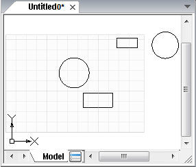
View is a combination of the size, position and orientation of a drawing fragment on the screen.
There are different tools and methods allowing you to orient in the document when you edit it. You can zoom or pan the working area for visual control of changes in the document; you can save a selected view for further display or printing; you can separate the working area of a document into several non-overlapping viewports to display different drawing fragments at the same time.
The main methods to change the document display on the screen are zooming and panning.
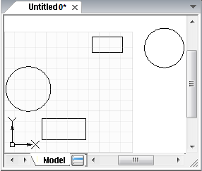
Zoom command enlarges the view of a drawing segment for better detailing or decreases it to display more of the drawing. Absolute sizes are not changed during zooming.
Pan command allows you to pan the drawing without decreasing or enlarging it.
Zoom and Pan commands are available in the View – Zoom menu or on the Zoom toolbar. For your convenience, most frequently used commands are on the Main toolbar and in the status bar.
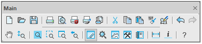
For more convenience, the most often used commands are also available in the Main toolbar and in the status bar.
note: You can zoom using the mouse wheel. Moving the mouse with the wheel pressed and held allows panning.
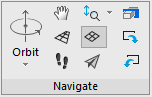
 Ribbon: View – Navigate >
  Pan
Pan
Menu: View – Zoom > Pan
Toolbar: Main –
Status bar –
 Command line: PAN, VIEWPAN
The mode to pan the image, occurs when you move the cursor with pressed left button, the image is moved dynamically to horizontal, vertical and diagonal directions. The scale of the document is not changed.
After starting the command, the cursor has the  shape.
With the left button pressed, the cursor has the  shape. In a perspective projection, the center relative to which the movement will be carried out is highlighted with a colored icon - a blue sphere
  .
.
To exit from pan mode, press the ESC or ENTER buttons.
Status bar –  Navigate
Command line: ZOOM, Z
Turns on the mode in which you can increase an object’s size on the screen by moving the mouse up and decrease it by moving it down. All available options are displayed in the command line:
Specify corner of window or
[All/Center/Dynamic/Extents /Scale/RScale/Window/Object] <real time>:
Command options:
|
All |
Displays the entire document on the screen, even if some of its objects are outside the established limits. Identical to calling the In this document display mode, not only the boundaries of the drawing are taken into account, but also the boundaries of the established document limits:
|
|
Center |
Places the image in the center of the screen. Scale of the document is not changed, only the image is panned. Displays the image in the center in the specified point with given scaling coefficient or height. Identical to launching the Setting height value less than current one leads to image increase. Setting larger value results in image reduction |
|
Dynamic |
Changes scale of the image on the screen in real time. Identical to calling the The cursor’s movement enlarges the image on the screen, if the left button of mouse is pressed and the cursor goes. The image decreases on the screen, if the left button of the mouse is pressed and the cursor goes down. |
|
Extents |
Displays the entire document inside its borders. Identical to calling the Borders of the specified document limits are not taken into account (in comparison with All):
|
|
Previous |
Consecutive display of previous views on the screen. |
|
Scale |
Changes the scale of the document using the precise scale factor. Identical to calling the The image on the screen is decreased or increased according to the specified document limits and the value. |
|
RScale |
Changes the document scale using the precise scale factor. The image on the screen is decreased or increased relative to the limits of the current document view and according to the specified value. |
|
Window |
Specifies display area of the document using two opposite corners of a rectangular frame. Identical to calling the |
|
Object |
Displays selected objects of the document on the screen. Identical to calling the Select one or several objects on the screen after you select the Object option. The image is displayed after all objects are selected and the ENTER button is pressed. If objects were selected beforehand – the display of image is reconstructed after the Object option is selected. |


Ribbon: View – Navigate >  Realtime
Menu: View – Navigation >  Zoom realtime
Toolbars: Main, Navigate –
Status Bar – 
 Command line: ZOOMD, VIEWZOOMDYNAMIC
Turns on the interactive image zooming mode, in which moving the mouse cursor with the left button pressed and held up the screen enlarges the view on the screen, and moving downward – reduces it.
After starting the command from the View menu or the Main toolbar, the cursor looks as follows:  .
.
Releasing the mouse button suspends the zoom, you can move the cursor to a different position, and then click again to continue zooming in the new position.
To exit the zoom mode, press ESC or ENTER.
note: In addition, it is convenient to zoom in by rotating the mouse wheel. In this case, the zoom step can be set in the Mouse settings – 3D Orbit settings – Mouse wheel to rotate 3D orbit of the Options dialog, box
Ribbon: View – Navigate >  Window
Menu: View – Navigation > Zoom Window
Toolbars: Main, Navigation –
Status bar –
Command line: ZOOMW
Sets the display area of the document by specifying two opposite corners of a rectangular frame.
In the process of specifying, for precise positioning of the window, it is convenient to use a one-time object snap from the context menu calling it by clicking the right mouse button while holding CTRL (or SHIFT).
Ribbon: View – Navigate >  Scale
Scale
Menu: View – Navigation >  Zoom scale
Toolbar: Navigation –
Changes the scale (zoom rate) of a document by specifying the exact scale factor.
The screen image is enlarged or reduced by a specified value relative to the specified document limits.
Ribbon: View – Navigate >  Zoom 1:1
Menu: View – Zoom > Zoom 1:1
Command line: ZOOM1, VIEWZOOM1X1
An image is scaled so that one pixel on the screen corresponds to one image point according to the specified DPI value.
Ribbon: View – Zoom >  Center
Menu: View – Zoom > Center
Toolbar: Zoom –
Displays image in the center in the specified point with given scaling coefficient or height.
Command prompts:
Specify center point:
Enter magnification or height <200.00>:
First specify the point that will be the center of zoomed fragment, and then set magnification or height. One can enter numeric value in the command line or determine height by specifying two points on the screen.
Setting height value less than current one leads to image increase. Setting larger value results in image reduction.
Zoom All
Ribbon: View – Navigate >  Zoom All
Menu: View – Zoom >  Zoom All
Toolbar: Main –
Status bar: 
Hotkeys: ALT+0
Command line: ZOOMALL, VIEWZOOMALL
Displays the whole document, even if some objects are outside the specified limits.
Ribbon: View – Navigate >  Zoom Object
Menu: View – Zoom >  Zoom Selected
Toolbar: Main –
Command line: FITSEL, FITSELECTED
Displays the selected objects.
Zoom Window
Ribbon: View – Navigate >  Zoom Window
Menu: View – Zoom >  Zoom Window
Toolbar: Main –
Status bar – 
Command line: ZOOMW
Selects an area on the screen, the area is specified with two opposite corners of the rectangular frame.
Ribbon: View – Navigate >  Zoom In
Menu: View – Zoom >  Zoom In
Command line: ZOOMIN
Doubles the scale.
Ribbon: View – Navigate >  Zoom Out
Menu: View – Zoom >  Zoom Out
Command line: ZOOMOUT
Decreases the scale by half.
Ribbon: View – Navigate >  Extents
Menu: View – Navigation > Zoom Extents
Toolbar: Navigation –
Displays the entire document on the screen within its extents.
In this mode of displaying a document (in contrast to the All option), the boundaries of the set document limits are not taken into account.
Ribbon: View – Navigate >  Previous
Menu: View – Navigation > Zoom Previous
Toolbar: Navigation –
Sequential display of previous views on the screen.