De
De 

-
-
-
-
-
-
-
-
-
-
-
-
-
-
-
-
-
-
-
-
-
-
-
-
-
-
-
-
Horizontal, Vertical and Aligned Dimensioning
-
-
-
-
-
-
-
-
-
-
-
-
-
-
-
-
-
-
-
-
-
-
-
-
-
-
Horizontal, Vertical and Aligned Dimensioning
In the following examples, horizontal, vertical and aligned dimensions are created by using the Auto command.
 Ribbon: Home, Annotate - Dimensions >
  Linear
 Menu: Dimensions –
 Auto
Auto
Toolbar: Utilities –
 Command line: DIMLINEAR
Setting linear dimensions with a horizontal, vertical or rotated dimension line.
萏Ѝ萑ﺛ葞Ѝ葠ﺛ࠵漀(.�� �� ��
1. Specify the starting points of the first and second leaders or press Enter to select an object.
2. Select the dimensioning option in the command line or context menu.
3. Specify the position of the dimension line.
Command options:
|
Mtext |
Enters multiline text. The Text Format bar opens. |
|
Text |
Enters or changes dimension text in the command line. |
|
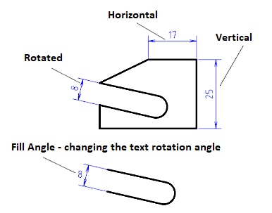
Horizontal |
Sets a horizontal dimension. |
|
Vertical |
Sets a vertical dimension. |
|
Rotated |
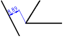
Sets the dimension at a certain angle. · Specify the rotation angle of the dimension line on the screen or in the command line. |
|
Fill Angle |
Changes the rotation angle of the dimension text. · Specify the rotation angle of the dimension text on the screen or in the command line. |
Setting horizontal, vertical and parallel dimensions
In the examples below the Auto command is used for setting horizontal, vertical and parallel dimensions.
Ribbon: Home, Annotation – Dimensions >  Auto
Auto
Menu: Dimensions –  Auto
Auto
Toolbar: Utilities, Dimensions –
 Command line: MDIM
To dimension you can use also the Horizontal, Vertical and Aligned dimension commands.
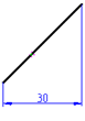
To specify the horizontal dimension of the line:
1. Start the Auto command.
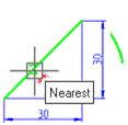
2. Place the cursor over the line to show its dynamic highlighting and display the character  . Left click to confirm the dimensioning:
3. Move the cursor down to change the character to  :
:
4. Left click to set the position of the dimension line:
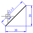
To specify the vertical dimension of the line:
1. Place the cursor over the line to show its dynamic highlighting and display the character . Left click to confirm the dimensioning:

2. Move the cursor to the right to change the character to :
3. Left click to set the position of the dimension line:
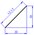
To specify the aligned dimension of the line:
1. Place the cursor over the line to show its dynamic highlighting and display the character . Left click to confirm the dimensioning:
2. Move the cursor to the left to change the character to :
3. Left click to set the position of the dimension line:
For dimensioning the arc length using characteristic points:
1. Start the Auto command.
2. Place the cursor over the arc to show its dynamic highlighting:
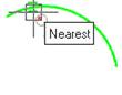
3. Move the cursor near to the endpoint of the arc. When the snap marker appears, left click to choose the endpoint of the first extension line of the dimension:
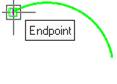
4. Move the cursor to the other endpoint of the arc and left click to choose the endpoint of the second extension line of the dimension:
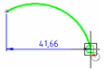
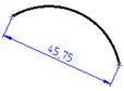
5. Move the cursor to the middle of the arc to display the character :
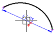
6. Move the cursor down and to the left to change the character to :
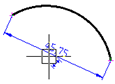
7. Left click to set the position of the dimension line:
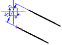
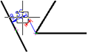
For dimensioning between two parallel line segments:
1. Start the Auto command.
2. Select the lower line segment by highlighting it and left click:
3. Select the top line segment by highlighting it and left click when the horizontal character appears:
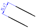
4. Move the cursor up and to the left to change the character to :
5. Left click to set the position of the dimension line:
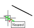
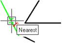
To draw the dimension from a point to a line segment:
1. Start the Auto command.
2. Select the lower line segment by highlighting it and left click:
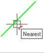
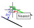
3. Select the endpoint of the second line segment using the snap:
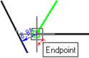
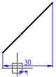
4. Move the cursor up and to the left:
5. Left click to set the position of the dimension line: