
 De
De 

-
-
-
-
-
-
-
-
-
-
-
-
-
-
-
-
-
-
-
-
-
-
-
-
-
-
-
Setting Viewport Border for Underlay
-
-
-
-
-
-
-
-
-
-
-
-
-
-
-
-
-
-
-
-
-
-
Setting Viewport Border for Underlay
 Ribbon: Insert –Reference – Clip >
  Underlay Clip
Menu: Modify – Clip >  Underlay
 Command line: UNDERLAYCLIP
The command allows you to clip underlays inserted in a drawing so that only its desired part is displayed on the screen and plotted.
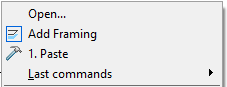
In pre-selection of the underlay for more convenient work the command of setting the viewport border becomes available in the context menu:
Setting the underlay viewport border impacts only on its display in the current document, the underlay itself is not changed.
The underlay clip is identical to the clip of a bitmap image and is carried out by using a polygon contour (rectangle, polygon or closed polyline), whose vertices lie inside the image border.
It is acceptable to assign different clip boundaries for different underlay insertions, but each insertion can have only one boundary.
The underlay clip can be disabled to display the original image, and then enabled again to display the clipped image. The clipping boundaries can be overridden. When setting a new clipping boundary, the old boundary should be deleted.
After deleting the clipping boundary, the underlay is displayed on the screen in its original boundaries.
To control the display of the underlay boundary, use the system variables PDFFRAME and DWFFRAME – depending on the type of underlay file. The variable value 0 disables the display of underlay boundary. To enable the boundary display, you should assign 1 value to the variable. When assigning 2 value to the system variable, the boundary is displayed but not printed.
Command options:
|
? |
Opens additional options for selecting objects. |
|
Select polyine |
Defines the boundary with the selected polyline. The polyline should be created in advance and cannot intersect itself. For arc segments of the polyline, their chords are used as a clipping boundary. |
|
Polygonal |
Defines a polygonal clipping boundary by sequential specifying the polygon vertices. When specifying the second and the next vertex points, the command line displays the prompt: Next point or [Undo]: Option: Undo - Sequential cancellation of the specified points of polygonal area vertices. |
|
Rectangular |
Defines a rectangular border of display boundary by specifying the opposite corners of the rectangular. |
|
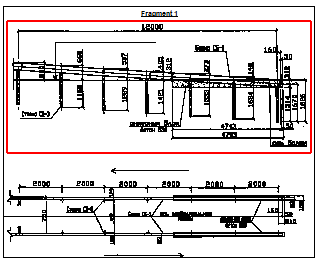
Defining rectangular border of display boundary |
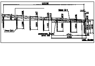
Displaying underlay after defining display boundary |
|
|
|
Command queries when defining a rectangular border:
|
Select a block or X-reference or [?]: |
Select bitmap, press ENTER. |
|
[Select polyline/Polygonal/Rectangular] <Rectangular>: |
Press ENTER. |
|
Define the first corner: |
Define the first corner. |
|
Opposite corner: |
Define the second corner. |
Command queries when defining a polygonal border:
|
Select a block or X-reference or [?]: |
Select bitmap, press ENTER. |
|
[Select polyline/Polygonal/Rectangular] <Rectangular>: |
Select option Polygonal. |
|
First point: |
Define the first point. |
|
Next point or [Undo]: |
Define the second point. |
|
… |
… |
|
Next point or [Undo]: |
Define the last point and press ENTER. |
Command queries when defining a polyline border:
|
Select a block or an external reference or [?]: |
Select bitmap, press ENTER. |
|
[Select polyline/Polygonal/Rectangular] <Rectangular>: |
Select option Select polyline. |
|
Select polyline: |
Select the option. |
To enable/disable clipping:
1. In the menu Modify – Clip select ON or OFF command.
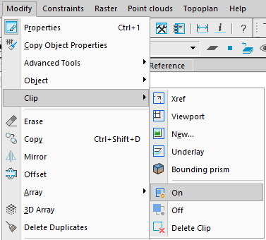
2. In response to the query in the command line Select block or external reference or [?]: specify underlay and press ENTER.
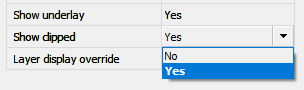
It is also possible to switch the clipping display in another way: select the underlay and switch the Display Clipped option on the Properties panel.
To modify the clipping boundary:
1. In the menu Modify – Clip select the New command.
2. In response to the query in the command line Select block or external reference or [?]: specify underlay and press ENTER.
3. In response to the query in the command line Delete the previous boundary(ies)? [Yes/No] <yes>: select Yes option or press ENTER.
4. In response to the query in the command line [Select polyline/Polygonal/ Rectangular] <Rectangular>: select the relevant option and define a new clipping boundary.
Attention! It is possible to create a new clipping boundary only if the old one is deleted.
To delete the clipping boundary:
1. In the menu Modify – Clip select the Delete command.
2. In response to the query in the command line Select block or external reference or [?]: specify underlay and press ENTER.