
 De
De 

-
-
-
-
-
-
-
-
-
-
-
-
-
-
-
-
-
-
-
-
-
-
-
-
-
-
-
Setting of the Show Boundary for the Block or External Reference
-
-
-
-
-
-
-
-
-
-
-
-
-
-
-
-
-
-
-
-
-
-
Setting of the Show Boundary for the Block or External Reference
 Ribbon: Insert – Reference – Clip >
  XReference Clip
Menu: Modify – Clip >  XRef
XRef
 Command line: XCLIP
The command sets the clipping contour of the show boundary to display the section of the inserted block or external reference.
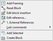
When a block or external reference is selected, the command to show boundary becomes available from the context menu for your convenience:
The command doesn’t change the objects of the block or external reference (the definition of the block or external reference remains unchanged). Creation of the clipping contour affects only the display block or an external reference in the current document.
If a block or external reference has been inserted more than once, it is possible to specify different clipping contours for each entry, but each entry can have only one contour.
Clipping of the block or external reference is carried out by a polygonal contour: rectangle, polygon or closed polyline.
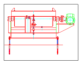
The XCLIPFRAME system variable is designed to set the visibility of the boundary of the clipping contour. If the system variable is set to a value of 1, the boundary of the clipping contour will be displayed on the screen. You can select it and print it out. If the system variable is set to a value of 0, the visibility of the boundary will be turned off (set by default).
|
Display of the boundary of the clipping contour is turned on (system variable XCLIPFRAME =1) |
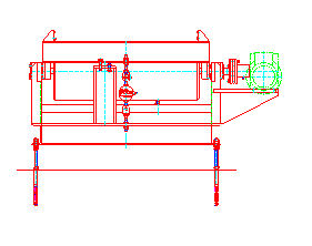
Display of the boundary of the clipping contour is turned off (system variable XCLIPFRAME =0) |
|
|
|
You can turn off the clipping of the block or external reference to display the full entry and then turn it on again to display only the clipped area.
A clipped section of the block or external reference can be copied, moved and rotated in the same way as an entry of the block or external reference that is not clipped. The clipping contour is copied, moved or rotated with the entry.
The clipping options also extend to attached references: when the main reference is clipped, all attached references will be clipped too.
The clipping contour can be redefined. Set the new clipping contour to remove the old contour.
After removing the clipping contour, the block or external reference is displayed on the screen in full.
Options:
|
? |
Calls additional options to select the objects. |
|
|
On |
Mode displays a clipped section of the block or external reference. |
|
|
Off |
Mode displays the full entry of the block or external reference. |
|
|
Clip depth |
Sets near and far clipping planes for the external reference or block. Objects beyond the limit of the contour set by planes of the space will not be displayed on the screen. This option calls the following prompt in the command line: Specify point for front clipping plane or [Distance/Remove]: Options: Distance - Create a clipping plane, passes at a prescribed distance parallel to the clipping contour. Remove - Delete near and far clipping planes. |
|
|
Delete |
Deletes the clipping contour for the selected entry of the block or external reference. This option deletes the clipping contour and clipping plane. |
|
|
Generate Polyline |
Automatically creates a polyline whose vertices match the vertices of the clipping contour. This option is used to change the current clipping contour: the created polyline is edited by the PEDIT command (the Modify menu – Object > Polyline). Then the edited polyline is used to change the existing clipping contour so that it is based on the new contour. |
|
|
New |
Creates a new clipping contour. This option calls the following prompt in the command line: [Select_polyline/Polygonal/Rectangular] <Rectangular>: Options: Select polyline - Set the limits contour by the selected closed polyline. The polyline should be created previously and consist of straight-line segments. Polygonal - Set the polygonal contour of the show boundary by sequenced specifying of the polygonal vertices. When you set the second and next vertices, you can see the following prompt in the command line Specify next point or [Undo]: Undo - Sequenced cancelling of the specified points of the polygonal vertices. Specified first point cannot be cancelled. Rectangular - Set the rectangular contour of the show boundary by sequenced specifying of the opposite rectangular vertices. |
|
|
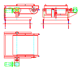
External reference before setting of the show boundary |
External reference after the setting of the show boundary |
|
|
|
The command prompts when you specify a rectangular boundary:
|
Select block or X-references or [?]: |
Select the block or reference and press ENTER. |
|
Enter clipping options [ON/OFF/Clip_depth/Delete/generate_Polyline/New] <New>: N |
Choose New or press ENTER. |
|
[Select_polyline /Polygonal/Rectangular] <Rectangular>: |
Press ENTER. |
|
Specify first corner: |
Specify the first corner. |
|
Specify opposite corner: |
Specify the opposite corner. |
The command prompts when you specify a polygonal boundary:
|
Select block or X-references or [?]: |
Select the block or reference and press ENTER. |
|
Enter clipping options [ON/OFF/Clip_depth/Delete/generate_Polyline/New] <New>: N |
Choose New or press ENTER. |
|
[Select_polyline /Polygonal/Rectangular] <Rectangular>: |
Choose Polygonal. |
|
Specify first point: |
Specify the first point. |
|
Specify next point or[Undo]: |
Specify the second point. |
|
… |
… |
|
Specify next point or[Undo]: |
Specify the end point and press ENTER. |
The command prompts when you specify a boundary by polyline:
|
Select block or X-references or [?]: |
Select the block or reference and press ENTER. |
|
Enter clipping options [ON/OFF/Clip_depth/Delete/generate_Polyline/New] <New>: N |
Choose New or press ENTER. |
|
[Select_polyline /Polygonal/Rectangular] <Rectangular>: |
Choose Select polyline. |
|
Select_polyline: |
Select polyline. |
To turn on/off clipping of the block or external reference:
1. In the Modify menu click Clip and then On or Off commands.
2. In reply to the prompt in the command line Select block or X-references or [?]: Select the entry and press ENTER.
To change the clipping contour of the block or external reference:
1. In the Modify menu click Clip and then the New command.
2. In reply to the prompt in the command line Select block or X-references or [?]: Select the entry and press ENTER.
3. In reply to the prompt in the command line Delete old boundary(s)? [Yes/No] <Yes>: Select Yes or press ENTER.
4. In reply to the prompt in the command line [Select_polyline/Polygonal/Rectangular] <Rectangular>: Select the required option and set the new clipping contour.
note! It is possible to create a new clipping contour if the old contour is deleted.
To delete the clipping contour:
1. In the Modify menu click Clip and then Delete command.
2. In reply to the prompt in the command line Select block or X-reference or [?]: Select entry and press ENTER.