
 De
De  Es
Es  Fr
Fr 

-
-
-
-
-
-
-
-
-
-
-
-
-
-
-
-
-
-
-
-
-
-
-
-
-
-
-
-
Dimensioning with a Single Command
-
-
-
-
-
-
-
-
-
-
-
-
-
-
-
-
-
-
-
-
-
-
-
-
-
-
-
-
-
Dimensioning with a Single Command
Dimensioning with a Single Auto Command
 Ribbon: Home, Annotate – Dimensions >
  Auto
Auto
Menu: Dimensions – Auto
Auto
Toolbar: Utilities –
 Command line: MDIM
You can set all dimensions in nanoCAD using a single command – Auto (the Dimensions menu) or Dimensions (on the Utilities and the Dimensions toolbars).
It is recommended to turn on the snap mode to maximise the facilities for dimensioning with a single command; set the required type of snap as a permanent snap. Switch on the To turn the object snap “Nearest” on automatically during an insert of objects option in the nanoCAD – Options dialog box on the Main tab of the Edit section (the Tools menu – Settings parameters).
Start the Auto command and select any dimensions from the context menu by right clicking:
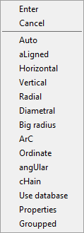 ,
,
or by selecting the appropriate option in the command line:
Insert dimension or [Auto/aLigned/Horizontal/Vertical/Radial/Diametral/Big radius/ArC/Ordinate/angUlar/cHain/Use database/Properties/Groupped]:
You can also set dimensions on the drawing directly after starting the Auto command.
When you move the cursor over any graphic entity (segment, segment of polyline, arc or circle) it will be highlighted automatically:
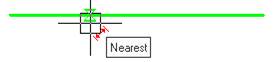
When the graphic entities are highlighted, nanoCAD displays the secondary symbols near the cursor that serve as prompts for the user. The secondary symbols indicate what dimension will be drawn if you left click on the graphic entity:
 - Aligned dimension.
 - Horizontal dimension.
 - Vertical dimension.
 - Diameter dimension.
 - Radius dimension.
 - Angle dimension.
 - Base dimension.
This method is used for dimensioning relating to a graphic primitive.
1. To quickly draw the dimensions that relate to a graphic primitive, you can turn off the object snap mode.
2. When you move the cursor along the highlighted primitive, the corresponding snap markers are displayed at its characteristic points. You can use it to specify the initial points of the extension lines:
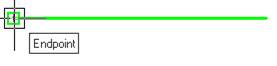
This method is used for dimensioning the elements of a drawing consisting of several graphic primitives.
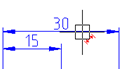
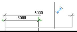
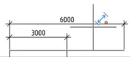
nanoCAD allows you to place the dimensions at given distances from each other, not only in base dimensions, but also at linear dimensioning. The distance by which the new dimension should be spaced from the existing one, is specified by a base-line spacing option in the Modify dimension style dialog box on the Lines tab.
To do this, it is necessary to specify the position of the dimension line and slowly move the cursor from the existing dimension line. When you draw near a specified distance, the new dimension line will be “attracted” to the required position. The color of the secondary character displayed near the cursor changes from red ( ,
,  or
or  ) to blue (
 ,
,  or
or  ):
):
|
Dimension line is not at the specified distance |
Dimension line is at the specified distance |
|
|
|
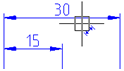
At dimensioning, you can set the extension line oblique by holding the CTRL key and moving the cursor in the desired direction.
To change the position of the dimension text, hold the SHIFT key and move the cursor to the first or second extension line (by default, the dimension text is located in the center of the dimension line).
During dimensioning, you can use the Edit dimension dialog box to specify the required properties and options for the executable dimension. To do this, it is necessary to select the Properties option in the command line or context menu. The dimensioning command is not interrupted.
To finish dimensioning, press ESC or select Cancel from the context menu.
You can dimension chamfers and fillets during their creation. Turn on the Measure chamfer or Measure fillet mode in the Chamfer or Fillet dialog box.