De
De 

-
-
-
-
-
-
-
-
-
-
-
-
-
-
-
-
-
-
-
-
-
-
-
-
-
-
Correction by Four Points
-
-
-
-
-
-
-
-
-
-
-
-
-
-
-
-
-
-
-
-
-
-
-
-
-
-
-
Correction by Four Points
 Ribbon: Raster – Crop >
  4 point correction
Menu: Raster –  4 point correction
Toolbar: Raster –
 Command line: FRAMING
The command is used for correction of scanned images with frame. It is suggested that the image frame and its content are distorted equally.
To perform this procedure, specify the desired frame size – its height and width, and the appropriate current position of the frame corner dots on the image. After correction the image is transformed so that the frame corners are moved to the rectangular frame corners of the specified size, whose sides are parallel to image sides.
If no image is selected, then this command processes all visible images located on unlocked layers.
To perform four point correction:
1. Select the images to correct by four-point correction. If no image is selected, then this command processes all visible images located on unlocked layers.
2. Start the command. The 4-point Correction dialog will be displayed:
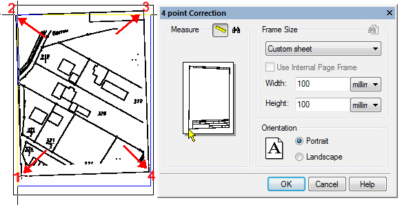
3. Click the Find frame  button. If the program is able to find the drawing frame, then you will see a blue polygon over the image close to the raster lines. If a frame is not found specify it manually.
4. To specify the frame corners manually, press the  button and click the frame corners on the image. These points can be specified in an arbitrary order because the program always sorts them so they form the frame without intersections. Watch the red rubberline to control, press BACKSPACE to go to previous frame corner if necessary.
5. In the Frame size field specify Width and Height.
6. Select orientation – Landscape or Portrait.
7. Press OK.
Find closest format button  starts searching closest standard paper format.
Or you can select format manually in Frame Size combo-box.
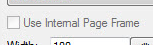
For standard paper formats you can use the Use internal frame option to correct frame size depending on paper format settings. Internal frame size can be defined in Papers section of the Options dialog ( Tools - Options).
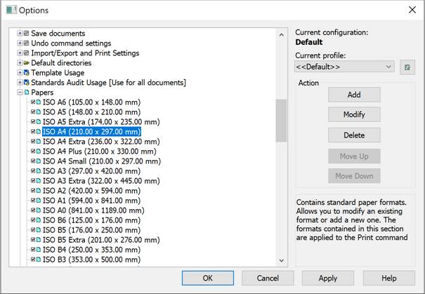
Set the internal page frame size:
1. Select paper format in Paper formats section.
2. Press Modify button.
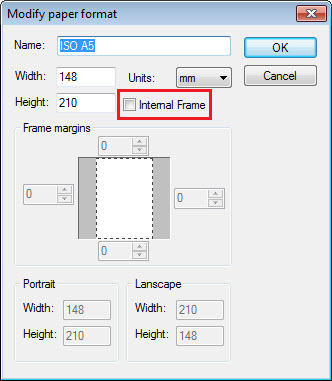
3. In the Modify paper format dialog - set Internal frame and specify margins in Frame margins fields.
For paper formats without internal frame specified, the Use Internal Page Frame option in 4-point Correction dialog will be disabled.