
 De
De 

-
-
-
-
-
-
-
-
-
-
-
-
-
-
-
-
-
-
-
-
-
-
-
-
-
-
-
-
-
-
-
-
-
Trace Polyline
-
-
-
-
-
-
-
-
-
-
-
-
-
-
-
-
-
-
-
-
-
-
-
Trace Polyline
 Ribbon: Raster – Trace – Trace >
  Line Following
Menu: Raster – Trace >  LineFollowing
 Command line: LFCMD
 This functionality is available only in the Raster module
The method belongs to the forced trace commands.
The method allows you to trace arbitrary raster lines, approximating them with a vector polyline. When tracing, specify a point on the raster line, and the command automatically follows this line (the tracing direction must be determined) to the nearest node point of the line or to the intersection point and creates an approximating vector polyline - a polyline consisting of linear segments. The node point of a raster line is either its endpoint or the point of intersection with another raster object. Thus, in one step, a part of an arbitrary raster line bounded by two node points is traced – a raster polyline segment. One trace step can create an arbitrary number of segments, the number of which depends on the line complexity and the trace settings.
After tracing each polyline segment, select the further direction of tracing or complete the procedure. Direction is selected by specifying a point on the next raster curve segment adjacent to the last traced segment. The steps and polyline segments can be undone.
The command provides for the mode in which the direction of continuing trace is determined automatically. In this mode, the program offers one of possible directions by showing a special marker on the segment selected as a continuation. Within a specified period of time (by default, the waiting time is 0), you can choose another direction or agree with the proposed one. If the direction is not selected, then after the waiting time has elapsed, the program will automatically continue tracing in the selected direction.
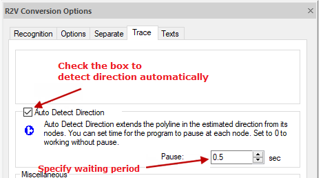
Setting auto detect direction
The tracing of raster polylines is influenced by the parameters set in the R2V Conversion Options dialog box on the Options tab: Max. thickness, Max. Break and Accuracy, which specify the maximum thickness of the raster polyline, the size of the ignored break, and the accuracy of the raster polyline approximation.
The color and width of the polyline created by tracing depend on the checked Use table box and specified values of parameters in the Separation tab in the R2V Conversion Options dialog.
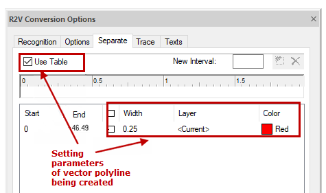
Setting parameters of vector polyline being created
Context menu commands when tracing polyline
|
Command |
Description |
|
Enter |
Completes the polyline trace process and selects the polyline. The command continues. |
|
Cancel |
Stops the tracing process and cancels all work done. In addition, the tracing process is interrupted by pressing ESC. |
|
BackStep |
Undoes the last tracing step. |
|
BackSegment |
Undoes the last polyline segment. |
|
Direction |
Inverts the tracing direction. |
|
DrawLine |
Adds a line segment to a polyline without tracing. To add multiple segments, press SHIFT. |
|
Center |
Zooms the image to show the last added polyline vertex in the screen center. |
The order of tracing a polyline
1. Set the command parameters in the R2V Conversion Options dialog box;
2. Specify the trace mode (Make vector, Erase Raster etc.);
3. Run the polyline trace comamnd;
4. Pick points on the raster curve. When the Auto Detect Direction box is checked, a “rubber” line is drawn from the mouse cursor showing the current trace direction;
5. Manage the tracing process from the context menu;
6. To complete the polyline creation, select Enter or press ENTER;
7. To exit the command, press ESC.
Tracing polyline with orthogonal segments
When tracing raster polylines, you can use the orthogonalization mode, which allows you to align the generated polyline segments at a predefined base angle:
1. In the R2V Conversion Options dialog box, when tracing, check the Line Follow Orthogonalization box on the Trace tab;
2. Check the Auto Estimate Base Angle box or set the first segment direction in the Base angle field (or using  button measure it on the screen);
3. Decrease the Accuracy value in the Options tab to avoid creating superfluous segments;
4. Select the required trace mode and run the polyline trace command;
5. Specify the point on the screen to start the trace.
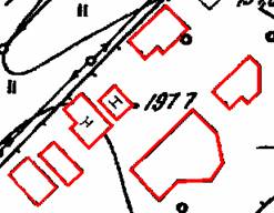
Results of trace with orthogonalization
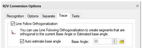
Setting orthogonalization when tracing