
 De
De  Es
Es  Fr
Fr  Pt
Pt 

Tuning Program Parameters
 nanoCAD Button -
  Options…
Ribbon: Manage – Customization – Options…
Menu: Tools – Options…
Toolbar: Tools –
 Hotkeys: CTRL+9
Command line: OPTIONS, PREF
You can launch the command from the context (right-button) menu of the command line:
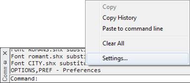
The command opens the Options dialog box:
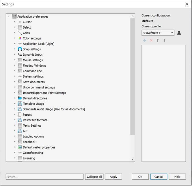
There is a tree of options, grouped by sections, in the left part of the dialog box.
To see/hide the parameters, either click twice on the section (subsection) name or click the  (unfold) /
  (fold) icon. The Collapse all button folds all sections and subsections to the initial view of the list.
The right side of the dialog box contains:
· information about the current configuration;
·  – a list of names of profiles available in the document. The profile selected in the list becomes the current one;
·  – a button for creating and managing profiles;
· buttons for creating, deleting, and moving parameters (become available if the selected parameter in the tree has the ability to change its value or can be moved up or down the tree):
·  – a button to add a parameter to the selected subsection;
·  – a button to delete the selected parameter;
·  – a button to move the selected parameter up one line;
·  – a button to move the selected parameter down one line.
· brief information about the selected setting.
The bottom of the dialog contains:
· Search field;
· Collapse all – a button to hide all subsections of the program settings list;
· Apply – a button to apply changes without closing the dialog box;
· OK – a button to apply changes and close the dialog box;
· Cancel – a button to close the dialog box without applying changes.
You can change paths and formats in the Default Directories, Papers and Raster File Formats sections by double-clicking the parameter or using the parameter’s context menu (right-click – Edit).
 The section of graphic cursor setting.
|
Peremeter |
Description |
|
|
Sets the size of the crosshair as a percentage of the display size. The default value is 5%. |
|
|
The cursor crosshair size settings subsection. Contains the Cursor Crosshair Size setting—specifies the cursor crosshair size in pixels. The default is 4%. |
|
|
pickbox size in pixels. |
|
|
The cursor color settings subsection. Contains the following cursor color settings: · Default – the cursor color is inversely adjusted to the background color, including colored background; Custom – sets the cursor color using the Select Color dialog box. To change the color, double-click the White is set by default.
When setting the cursor color to grayscale, the cursor display in the drawing’s graphics area is inversely adjusted to the background color (it becomes dark on light backgrounds and light on dark backgrounds). Grayscale colors have identical RGB components, for example, Red = 127, Green = 127, Blue = 127. White (RGB 255, 255, 255) and black (RGB 0, 0, 0) are included in this color mode. · For any other combination of RGB components, the cursor color will be displayed according to the user-defined parameters. · 3D Style Colors – sets a 3D color style for the crosshair and cursor reticle. When a 3D color style is set, changing the color of the crosshair and cursor reticle is not possible. |
|
|
Switches object tooltips on/off. |

 Parameters of frames to select objects.
|
Parameter |
Description |
|
|
Sets the frame color. The default setting is |
|
|
Sets the fence color. The default setting is |
|
|
Sets the transparency of frame and fence. The defaultsetting is 70 %. |
|
|
Limits the number of objects that can be changed at one time in the Properties functional bar. Value can be changed from 0 to 32767. 0 – switch of the limit edited objects, but this can decrease performance in large drawings. The limit doesn’t affect to General section in Properties functional bar). The default value is 25000. |
|
|
Subsection to define the method of objects selection ina drawing. · Click and Click – defines a frame for selecting objects by specifying two diagonal points (two left-clicks are required to create a selection frame); · Press and drag – defines a frame for selecting objects by specifying one point and then moving the mouse cursor while holding down the left mouse button to select a second diagonal point, which is then specified by releasing the left mouse button (one left-click is required to create a selection frame); · Automatic detection – defines a frame for selecting objects automatically: either by two left-clicks or by press and drag. Allow press and drag for Lasso – enables/disables the lasso selection method. |
|
|
Enables/Disables the mode of saving selection of objects after modify commands: Move, Rotate, Scale, Mirror, Copy, Array. When this mode is enabled, the selection set includes: objects modified or created as a result of the Move, Rotate, Scale, Mirror, or Copy command, as well as selected source objects and objects created as a result of the Array command. Cancel the selection of objects by pressing the ESC key. |
|
|
Selection Preview Settings subsection. Contains the |
 (RGB 0, 128, 255).
 (RGB 128, 255, 128).
Subsection to set objects highlight style.
|
Parameter |
Description |
|
|
Specifies the highlighting method for objects included in the selection: · Line highlight style – specifies the line highlighting method: Dotted lines or Color; · Face highlight style – specifies the face highlighting method: Pattern or Color. |
|
|
Specifies the highlighting method for objects included in the selection preview: · Line highlight style – specifies the line highlighting method: Highlighting or Color; · Face highlight style – specifies the face highlighting method: Pattern or Color. |
 Subsection to set objects fading level.
|
Parameter |
Description |
|
|
Controls the dimming for all Xref-objects in a drawing. |
|
|
Specifies the fading intensity value for drawing objects during in-place reference or block editing. |
|
|
Controls the amount of fading for objects on locked layers. The option is synchronized with LAYLOCKFADECTL system variable. |
 Parameters of the grips of the selected objects.
|
Parameters |
Description |
|
|
Specifies the grip size in screen pixels. The default is 5. |
|
|
Setting a limit on the number of selected objects that display grips. This is necessary to improve performance, since if the drawing contains a large number of objects with a large number of grips (hatching, polylines), then selection of objects can take a long time. By default, the parameter is set to 100 (the value is stored in the GRIPOBJLIMIT system variable). |
|
|
Specifies the grips color. |
|
|
Specifies the grips color under cursor. |
|
|
Specifies the selected grips color. |
|
|
Specifies the color of grips for dynamic blocks. |
|
|
Subsection to control the ways of access to multifunction grips parameters (GRIPMULTIFUNCTIONAL system variable): · By pressing Ctrl – enables/disables cycling through grip editing commands by pressing the CTRL key. · By menu – enables/disables selection of editing commands in the grip’s dynamic menu, displayed when you hover over it. |

 The section for setting color for program components using the Color Settings dialog box. To change the color, double-click the parameter.
|
Parameter |
Description |
|
|
The color of background in model space. |
|
|
The color of layout in paper space. |
|
|
The color of background in paper space. |
|
|
The color of Grid points. |
|
|
The frame color that indicates a print area. |
|
|
The frame color that indicates the paper format edges. |
|
|
Block Editor background color. |
|
|
The color of Center mark for Virtual Trackball command. |
|
|
The color of Center mark for Pan command in PERSPECTIVE=1 mode. |
|
|
Subsection to configure color of dimension constraints: · Dimension lines – specifies color of dimension lines (DYNCONSTRAINTSCOLOR system variable); · Dimension texts – specifies text color (DYNCONSTRAINTSTXTCOLOR system variable). |
 Section for setting the visual style of the program interface:
|
|
Note |
|
To quickly preview the selected visual style, it’s convenient to use the Apply dialog button. |

 Defines the Snap settings.
|
Parameter |
Description |
|
|
The size of a cursor frame in snap mode. The default value is 10 pixels. |
|
|
Switches the aperture box on/off in the snap mode. |
|
|
Snap marker size. The default value is 5 pixels |
|
|
Turns on the display of a snap name. |
|
|
The color of the snap marker when snapping to a vector object. |
|
|
Sets color of object snap tracking marker in snap to vector object. |
|
|
Sets color of rays in snap to vector object. |
|
|
Enables/Disables the mode in which object snap is triggered when the crosshair (aperture) is located directly over a key point of the object, for example, over the end point of a line segment. |
|
|
Enables/Disables object highlighting for snapping. Note: Only objects whose key points correspond to activated (enabled) snaps are highlighted. |
|
|
Enables/Disables display of icons for all object snap points. Note: Only icons for activated (enabled) snaps are displayed. |
|
|
Enables/Disables simplified display of snap icons. |
|
|
Enables/Disables the mode for creating a temporary construction line for snapping, which is an extension of an arc, including elliptical ones. Activated when hovering over the arc’s endpoint. |
|
|
Enables/Disables the use of the CTRL key to temporarily disable snapping. |
|
|
Enables/Disables the display of snap point coordinates in the tooltip. |
|
|
Enables/Disables the mode for snapping only to the top object in 3D space. |


 Manages mouse input, dimension input, dynamic tooltips, and tooltip appearance.
|
Parameter |
Description |
|
|
Enables/Disables mouse input. |
|
|
Enables/Disables dimensions input. |
|
|
Subsection to control the display of tooltips in polar or Cartesian coordinate formats (DYNPIVIS system variable): · After starting to enter coordinate vlues – displays tooltips only when you start entering coordinate values (DYNPIVIS = 0). · When the command requests a point input – displays tooltips when the command prompts for a point input (DYNPIVIS = 1). · Always – always display tooltips, even in non-command mode (DYNPIVIS = 2). |
|
|
Sets tooltips parameters for mouse input. Polar or Cartesian input format – manages the display of tooltips in polar or Cartesian coordinate formats: · Use polar format – displays tooltips in polar coordinate format; · Use Cartesian format – displays tooltips in Cartesian format. Relative or Absolute input format – manages the display of tooltips in relative or absolute coordinate formats: · Use relative format – displays tooltips in relative coordinate format; · Use absolute format – displays tooltips in absolute coordinate format. |
|
|
Enables/Disables the display of dynamic input prompts. |
|
|
Sets the tooltip color. |
|
|
Sets the size of tooltips. The range is from -3 to 6. The default is 0. |
|
|
Sets the tooltips transparency. The default is 0%. |
|
|
Enables/Disables the display of Z coordinate. The Z coordinate other than 0 is displayed in the dynamic input field only when object snap mode is enabled. |

 The section manages the mouse parameters setting.
|
Parameter |
Description |
|
|
Subsection to set the rotation method of the orbit. Horizon lock – enables/disables model rotation constraints. If enabled, the Z-axis projection remains vertical in the screen plane when the model rotates. When disabled, model rotation is unlimited (VIEWHORIZON system variable). 3D orbit mouse sensitivity – adjusts the rotation speed. The minimum rotation speed is 25%, and the maximum is 400% of the nominal value. The default is 300%. Orbit center – Subsection to specify the orbital rotation center (target point) 3D Orbit and Free Orbit commands: · Visible objects – sets the orbital rotation center to the center of all visible objects in the graphic area. For example, if only a portion of a circle is displayed on the screen, rotation will occur around the center of this circle. · Visible parts of objects – sets the orbital rotation center to the center of all visible parts of objects in the graphics area. For example, if only a part of a circle is displayed on the screen, the rotation will be performed around the center of the part of the circle visible on the screen. |
|
|
Sets the zoom factor and direction using the mouse wheel. For factors greater than 1, rotating the wheel forward (away from you) zooms in; for factors less than 1, rotating the wheel zooms out. Setting a factor of 1 disables zooming using the mouse wheel. |
|
|
Subsection to override the right button function. Default mode – subsection that determines the behavior of the right mouse button (RMB) in normal mode, when no objects are selected or commands are running: · Repeat last command – disables the standard context menu. Right-clicking simulates pressing the ENTER key, i.e., serves to repeat the last command. · Shows Popup Menu – opens the standard context menu. Edit Mode – subsection that determines the behavior of the RMB in edit mode, i.e., when one or more objects are selected but no commands are running: · Repeat last command – disables the edit context menu. Right-clicking simulates pressing the ENTER key, i.e., serves to repeat the last command. · Shows Popup Menu – opens the edit context menu. Command mode – subsection that determines the behavior of the RMB in the command mode, i.e., while a command is running: · Sends “ENTER” – disables the command context menu. Right-clicking simulates pressing ENTER. · Shows Popup Menu – opens the edit context menu. · Shows Popup Menu when command options present – opens the command’s context menu only if the command line contains available options. If there are no options in the command line, right-clicking is equivalent to pressing ENTER. Shows Popup Menu after delay – enables/disables the mode that determines how long the right-click behaves based on the duration of the press. A short right-click is equivalent to pressing ENTER. A longer press displays the context menu. · Delay <250> ms – sets the duration in milliseconds for a right-click to display the context menu. The default is 250 ms. · Always show Popup menu when objects selected – if this setting is enabled, if one or more objects are selected, right-clicking always displays the context menu, regardless of the press duration. |
 Section to configure interface of the floating document window. The settings are applied only to newly unpinned windows; the appearance of already unpinned windows remains unchanged
|
Parameter |
Description |
|
|
Enables/Disables display of ribbon and menu bar in floating windows |
|
|
Enables/Disables display of the status bar in floating windows. |
The section sets the parameters of the command line.
|
Parameter |
Description |
|
|
Enables/Disables automatic selection of options after entering one or more characters in the command line. · Autoselect mode – sets the criteria for selecting an item in the auto-select list: · Don’t select – manual selection mode. · Select on prefix – matches the input with the beginning of a possible command line. Work options a) Search for insertions across the entire line disabled – selection from the list of command line options is performed if the entered ordered sequence of characters matches the beginning of the name of the selected option.b) Search for insertions across the entire line enabled – selection from the list of command line options is performed if the first character of the selected option matches (for example: zll – the ZoomAll command will be selected). · Always select – the first item will always be selected from the selected list of command line options. · Completion content – contents of the autocomplete list: · Complete system variables – enables/disables the display of system variables in the autocomplete list. · Complete blocks – enables/disables the display of block names in the autocomplete list. · Complete tools – enables/disables the display of commands from the toolbox in the autocomplete list. · Additional options – additional options for selecting an autocomplete list item: · Autocomplete during delay – enables/disables the mode for selecting the most suitable command line option before displaying the autocomplete list. · Completion list delay – sets the delay time for displaying the autocomplete list (AUTOCOMPLETEDELAY system variable). The default is 0.3 seconds. · Fuzzy complete – enables/disables intelligent search based on fuzzy logic: searches for parts of the input string throughout the entire command name with automatic correction of possible input errors. |
|
|
Sets the command line colors: · Default – command line colors are determined by the interface’s visual style; · Custom – specifies custom colors: · Command line background color – sets the background color; · Command line text color – set the command line text color. |
|
|
Enables/Disables the using of alternative font in the command line. |
|
|
Specifies font height in the command line. The default is 12 pixels |
 Video subsystem and graphic displaying settings.
|
Parameter |
Description |
|
|
Subsection to switch the used hardware graphics acceleration library: · OpenGL – uses the OpenGL hardware graphics acceleration library; DirectX – uses the DirectX hardware graphics acceleration library. By default, when selecting DirectX, DirectX 11 is activated. If it is not supported (for example, when running over RDP), DirectX 9 is activated. You can manually change the DirectX version using the DirectX Improved Compatibility Mode option or the NCGS_TOGGLE_DIRECTX command. |
|
|
Enables/Disables the jagged smoothing effect when displaying drawing graphics (antialiasing). Smoother line displaying. Setting will be applied for new opened or created document. This effect does not work when improved compatibility mode is enabled. |
|
|
Subsection for object rendering optimization settings. · Optimize rendering objects with linewidth – enables/disables the display of line widths while navigating the document (zooming, panning, etc.). · Optimize small details rendering – enables/disables the display of dots and other similarly sized graphics while navigating the document (zooming, panning, etc.). · Simplify text less than <2> pixels – sets the on-screen text display height in pixels, below which text objects are displayed in a simplified form (as a bounding rectangle). A drawing refresh may be required for the changes to take effect. · Min mipmap level size <512> pixels – sets the minimum detail level to speed up work with large rasters. |
|
|
Subsection to manage OpenGL settings. · Screen caching – sets for automatic and manual adjustments to hardware-accelerated OpenGL graphics. Changed settings will only apply to newly opened or created documents. It is recommended to close documents open in the program before changing the settings: · Generic – uses software for screen caching; · Accelerated – uses hardware acceleration for screen caching. · Improved compatibility mode – sets an improved compatibility mode for graphics display. This mode is a software emulation of OpenGL using basic Windows tools and eliminates interaction with the PC’s graphics hardware (which can significantly slow down the process of redrawing images on the screen). In this mode, a number of graphics display features are disabled, including antialiasing. The settings will only apply to newly opened or created documents. |
|
|
Subsection to manage DirectX settings. · Sets threshold texture size for texture cache – small raster images are displayed faster when stored in the PC’s video memory. This coefficient sets a limit on the size of images stored in video memory. An acceptable image is one whose largest dimension (vertical or horizontal) does not exceed the video memory size multiplied by this coefficient. Valid values for this coefficient are from 0.1 to 0.5. DirectX version used for render – the version of DirectX used. If this box is checked, DirectX 9 is used. When this box is unchecked, the default DirectX version is used. In most cases, this is DirectX 11, but if it is not supported by the system, DirectX 9 is used. You can also switch the DirectX version using the NCGS_TOGGLE_DIRECTX command. |
|
|
Subsection to manage the platform components settings that supports the creation of print previews in metafile (WMF) or bitmap (BMP) formats: · Metafile (WMF) – uses a metafile (WMF) image to generate the image in the preview window. · Bitmap (BMP) – uses a bitmap (BMP) image to generate the image in the preview window. |

The section to manage saving, auto saving and backup parameters.
|
Parameter |
Description |
|
|
List of acceptable formats used to save a file using the Save, Save as commands. |
|
|
The subsection to set a type of documents to which the file format selected in the Save in a format section is applied: · None – saving new documents using the Save and Save As commands in the file format last selected in the Save Document dialog. · For new documents – saving new documents using the Save command in the file format selected in the Save in a format section. · For all documents – saving both new and open documents using the Save and Save As commands in the file format selected in the Save in a format section. |
|
|
Subsection to set incremental saving – saving, when not a whole file is copied, but only its changed parts: · Off – a mode in which incremental saving will not be applied. A full save and full autosave will be performed. · Autosave – a mode in which a full save and incremental autosave will be performed. · Save and Autosave – a mode in which an incremental save and incremental autosave will be performed. |
|
|
Subsection to specify autosave and backup settings. Autosave every <5 min> – sets the automatic saving interval for the current document. A value of zero disables automatic document saving. Autosave folder – specifies the folder for saving autosave files. The default folder is C:\Users\User_name\AppData\Local\Temp. Create backup copy – enables/disables backup creation. Backup original – enables/disables the original backup creation. Backup folder – specifies the folder for saving backup files. By default, backup files are saved in the original file’s folder. Network Drive Compatibility Mode – enabling/disabling this setting allows saving files to certain network drives that do not support remote file renaming. Enabling compatibility mode will also prevent backup copies from being saved to these drives. To save backup copies, you must explicitly specify a local folder in the Backup folder setting. When working with regular network drives, this setting does not work; backup files are saved. |
|
|
Subsection of settings for saving file history. A mode of saving history is based on the file autosave mechanism. It can be needed if it is necessary to return to previous states of a document file, for example, if it was not save by mistake. Save file history – enables/disables file history preservation. Number of stored file versions <5> – specifies the number of file versions. File versions are stored for <15> days – specifies the storage period for history files. File history folder – specifies the folder for saving history files. By default, the folder is set to C:\Users\User_name\AppData\Roaming \Nanosoft\nanoCAD x64 26.0\UnsavedFiles. |
|
|
Subsection for setting mode to control simultaneous opening of files. Control when opening a file – enables/disables control mode when opening a file. User name – visible username. |
The section for Undo command settings.
|
Parameter |
Description |
|
|
Displays a preview of the result for each step of the Undo command. |
|
|
Clears the list of all Undo actions after saving a document. |
|
|
Filling the Undo command list with 2D navigation commands: Pan, Zoom, etc. |
|
|
Filling the Undo command list with 3D navigation commands: Orbit commands (including Shift + mouse middle button), 3D Walk, 3D Fly, Locator using. |
|
|
Groups undo for 2D and 3D navigation commands in single step. |
Import/Export and Print Settings
The section sets settings for import, export and print commands.
|
Parameter |
Description |
|
|
Manages the printing of objects temporarily hidden using the HIDEOBJECTS or ISOLATEOBJECTS commands. When the option is enabled, hidden objects in temporary isolation mode (system variable OBJECTISOLATIONMODE = 0) are printed; when disabled, they are not printed. By default, the option is disabled; temporarily hidden objects are not printed. |
|
|
Controls the way of processing “transformed” TTF texts output to different print devices, including creating PDF and similar output formats. The “Transformed” text – text that created with any of the following options applied: oblique angle, compression, stretch, rotation on any angle (excluding 0, 90, 180 and 270 degrees). · as text – text will be printed as text object with the same or similar font and attributes. This will keep the text string and makes it searchable, but may cause some visual differences from original representation. · as graphics – text will be converted to graphic primitives. The content of text string won’t be preserved. In some cases this could be helpful to avoid visual inconsistencies towards the original text representation. |
 Section for specifying paths to both default folders for storing system files and user folders.
The section sets folders where miscellaneous system files are stored –fonts, line types, hatch patterns, multiline styles, plot styles and configuration files, templates, etc.
nanoCAD searches files in Common files location folders, then in subfolder downwards. First found file will be used and search will be stopped.
In the Common files location subsection, the path to the Samples folder is indicated, in which sample files are posted that demonstrate individual nanoCAD capabilities.
|
|
Note |
|
Path to the Samples folder is not displayed in the Common files location subsection. |

When the program searches for files, folders are viewed in the order they are listed in the subsections of the Default directories section. The contents of the Common files location subsection are viewed first, then the contents of the next subsections in the order they are listed (from top to bottom). Folders in subsections are also viewed starting from the top one in the list and ending with the bottom one. At that, if the same file is located in different folders, the search stops as soon as the first copy of the file is found.
You can change search order using the Up and Down buttons. The Add, Delete buttons permit to add or delete folders including default ones. Note that PlotConfigs and PlotSyles sections can only be modified, not deleted or added new paths.
To change it, open the folder selection dialog by double-clicking the left mouse button on the path or by right-clicking and selecting the Modify option from the context menu.
To restore default folder search paths, you can use the UnSelect All button in the Profiles dialog (Manage menu - Options... >  Profiles button).
|
|
Attention |
|
All user settings will be lost when using the UnSelect All button!. |

Dialogs for opening/saving files in nanoCAD are dynamically adjusted to display standard (default) and custom folders. Depending on where in the program the open/save file dialogs are opened (in other words, what types of file formats the dialogs work with), the corresponding folders are displayed in the nanoCAD list of the transition area, the paths to which are specified in the Default directories section.
For example, with the same file search path settings, the lists of nanoCAD folders in the transition area of dialogs when opening drawing files (*.dwg) or loading linetype files (*.lin) will be different.
|
Parameter |
Description |
|
|
All files placed in this folder will be used primarily for all types files in Standard folders. Search in this subsection is carried out first. |
|
|
Path to folders with text fonts, linetypes, hatches, multiline styles. Default value: <C:\ProgramData\Nanosoft AS\nanoCAD x64 26.0\shx> |
|
|
Path to folders with nanoCAD template files. Default value: <C:\Users\User_name\AppData\Roaming\Nanosoft AS\nanoCAD x64 26.0\Templates> |
|
|
Path to folders with Plot Configuration files. Default value: <C:\Users\User name\AppData\Roaming\Nanosoft AS\nanoCAD x64 26.0\PlotConfigs> |
|
|
Path to folders with Plot Styles files. Default value: <C:\Users\User_name\AppData\Roaming\Nanosoft AS\nanoCAD x64 26.0\PlotStyles> |
|
|
Path to folders with PAT files. Default value: <C:\ProgramData\Nanosoft AS\nanoCAD x64 26.0\shx> |
|
|
Path to folders to search for Tool Palette files. Default value: <C:\Users\User_name\AppData\Roaming\Nanosoft AS\nanoCAD x64 26.0\ ToolPalette> |
|
|
Path to folders to extract and save used image files while importing PDF files: Default value: <C:\Users\User name\AppData\Roaming\Nanosoft AS\nanoCAD x64 26.0\PDF Import Images> |
|
|
Path to folders to extract and save used OCR template files. Default value: <C:\Users\User_name\AppData\Roaming\Nanosoft AS\nanoCAD x64 26.0\OCR> |
|
|
Paths to folders in which the program should search for script files. Default value: <C:\Users\User_name\AppData\Roaming\Nanosoft AS\nanoCAD x64 26.0\Scripts> |
|
|
Paths to folders in which the program should search for color books files. |
|
|
Source files for import. Default value: <C:\Users\User_name\AppData\Roaming\Nanosoft AS\nanoCAD x64 26.0\GeoFiles> |
|
|
Ready-made underlays for insertion into drawings. Default value: <C:\Users\User_name\AppData\Roaming\Nanosoft AS\nanoCAD x64 26.0\GeoUnderlays> |
|
|
Ready-made coverings for insertion into drawings. Default value: <C:\Users\User_name\AppData\Roaming\Nanosoft AS\nanoCAD x64 26.0\CoveringsLibrary> |
|
|
Path to folders in which the program should search for classifier files. Default value: <C:\Users\User_name\AppData\Roaming\Nanosoft AS\nanoCAD x64 26.0\classifier> |
 Section to specify templates for new documents and for import and export of documents.
|
Parameter |
Description |
|
|
Subsection for setting templates when creating new documents. · None – disables the use of templates when creating new documents. · Use default – uses the template file specified in the Default Template File section for new documents. · Ask for file – opens the Open Document Template File dialog box to select a template file. · Choose from list – opens the Select Template dialog box with a list of existing template files when creating a document. · Default Template File Name – specifies the template file to be used when the Use Default condition is specified. When launching nanoCAD, the Default.dwt template is used by default. · Templates Names List – generates a list of template files. |
|
|
Subsection to specify templates when importing documents. · None – disables the use of templates when creating new documents. · Use default – uses the template file specified in the Default Template File section for new documents. · Ask for file – opens the Open Document Template File dialog box to select a template file. · Choose from list – opens the Select Template dialog box with a list of existing template files when creating a document. · Default Template File Name – specifies the template file to be used when the Use Default condition is specified. When launching nanoCAD, the Default.dwt template is used by default. · Templates Names List – generates a list of template files. |
|
|
Subsection to specify templates when exporting documents. · None – disables the use of templates when creating new documents. · Use default – uses the template file specified in the Default Template File section for new documents. · Ask for file – opens the Open Document Template File dialog box to select a template file. · Choose from list – opens the Select Template dialog box with a list of existing template files when creating a document. · Default Template File Name – specifies the template file to be used when the Use Default condition is specified. When launching nanoCAD, the Default.dwt template is used by default. · Templates Names List – generates a list of template files. |
 For Export to File
 Section for managing the settings for using the standard.
|
Parameter |
Description |
|
|
The ban on connecting the standard file to the opened drawings. The option is selected by default. |
|
|
Permission to use the standard file for all opened documents. |
|
|
Specifies a DWS standard file (*.dws). In the Configure Standards dialog box (STANDARDS command), the assigned file will appear first in the list. |


 Contains standard paper formats.
Allows the modification of an existing format or addition of a new one. The formats in this section are used for printing.
Raster file formats which can be inserted with Image from File command.
|
Parameter |
Description |
|
|
A format for storing raster images. Stores graphic information in compressed form without loss of quality. The TIF format is most often used for high-quality graphics, scanned images, and drawings where sharp contrast between pixels and preservation of layers are important. |
|
|
A format for storing raster images. Stores graphic information in compressed form without loss of quality. The TIFF format is most often used for high-quality graphics, scanned images, and drawings where sharp contrast between pixels and preservation of layers are important. |
|
|
A format for storing TIFF raster images with georeferencing. Used for cartographic data. |
|
|
A format for storing raster images developed by Microsoft. Stores graphic information without data compression with high image quality, which is reflected in the file size. |
|
|
A format for storing raster images developed by Joint Photographic Experts Group. Stores graphic information in a compressed, lossy form. The JPEG format is most often used for photographs and images with smooth transitions of brightness and color. |
|
|
A format for storing raster images developed by Joint Photographic Experts Group. Stores graphic information in a compressed, lossy form. The JPEG format is most often used for photographs and images with smooth transitions of brightness and color. |
|
|
A format for storing raster images. Stores graphic information in a compressed form without loss of quality. Supports full-color images and transparency. The PNG format is used for drawings and graphics with sharp contrast between adjacent pixels. |
|
|
A format for storing raster images developed by ZSoft Corporation. Stores graphic information in a compressed form. |
|
|
A format for storing raster images. Stores graphic information in a compressed form without loss of quality. The format is limited to 256 colors, but supports animated images. Used for simple images and graphics with minimal colors. |
|
|
A constrained raster image format optimized for storing aerial and satellite images. The format efficiently compresses large images with high dynamic contrast. The ECW format stores the image coordinate system data in the image file itself. Reading and writing images up to 500 MB are available. |
 Section to specify a file with font for replacing.
|
Parameter |
Description |
|
|
Name of font file to replace a missing font in an opened document. |
|
|
Specifies rotation mode for text object editing. If checkbox is ON, then only text object is rotated. Otherwise, the entire drawing rotates. |
 Options for nanoCAD applications developers.
|
Parameters |
Description |
|
|
Resets ignored exceptions. The list of exceptions will be reset after restarting the program. |
|
|
Enables/Disables writing API protocols. |
|
|
Specifying the folder and file name of the API protocol. |
|
|
Specifying an action when calling not implemented API. · Do nothing · Show message box · Throw exception · OutputDebugString |
|
|
Specifying the developers’ email address. |
|
|
Folder for storing temporary files. The default folder is c:\Users\User_name\AppData\Local\Temp |


Section for setting up feedback with developers and support service.
|
Parameter |
Description |
|
|
Setting the mode for sending a log of statistical data on the use of nanoCAD. · Not to send – prohibition to send the log of statistical data; · Resolve sending – permission to send statistics log; · Resolve and report – permission to send statistical data log and advance information before sending. |
|
|
Enables/disables generating a problem report when errors occur that cause the program to crash |

 The section for setting the default raster image properties. These options are used to display a raster when they are not explicitly set. For example, when opening a raster image that does not have a resolution value.
|
Parameter |
Description |
|
|
Default resolution for images doesn’t contains resolution. |
|
|
Enables/disables transparency mode for monochrome images. |
|
|
Sets the maximum size of rasters that can be fully loaded into RAM. If the size is larger than the specified value, inline dynamic loading will be used, and rasters will be loaded in read-only mode (MAXRASTERSIZE system variable). The default size is 1024 MB, and valid values range from 0 to 2048 MB. This parameter is ignored for ECW images (limited to 64 MB). |

 Section for setting georeferences of raster images.
|
Parameter |
Description |
|
|
Using World or TAF file when inserting raster images. Inserting georeferenced raster images in World or TAF georeferencing files, if any. When inserting such rasters, the coordinates of the insertion point, the scale and the rotation angle are substituted automatically. It also creates a World file with geo-coordinates for each Raaster image saved from the External References Manager using the Save as command from the context menu |

Section for setting licensing parameters of the program and its modules.
|
Parameter |
Description |
|
|
Defining the procedure for checking product licenses: · NanCAD Plus; · NanoBIM; · NanoCorp; · NcBuild; · NcLand. |
|
|
Section for managing the availability of the program modules: · 3D geometric modeler and constraints – Subsection for switching the used geometric 3D kernel and constraints: · C3D – using 3D geometric kernel; · 3D modeler, 2D and 3D Constraints (C3D) – Enables/Disables loading 3D modeling modules, 2D and 3D constraints on C3D kernel. · Platform mode – subsection for displaying the running operating mode: · Common; · Construction; · Mechanica · Raster tools – enables/disables the Raster module, which includes full functionality for working with raster images and some point cloud commands. When disabled, only basic functionality will be available in the Point Cloud and Raster main menu items (as well as in the corresponding ribbon tabs): rotation, skew correction, correction, pencil, and eraser functions. · Topoplan – enables/disables loading of the Topoplan module, which includes functionality for editing topographic plans. |
|
|
Determines the order of requesting the license: first product, then corporate ones, or first corporate and then product ones. |
|
|
Determines the order of requesting the license: first “Engineering BIM” and then product and corporate ones. |
“Don’t show again” messageboxes
 Section to manage the display of warning message.
|
Parameter |
Description |
|
|
Enables/Disables messages when adding line types already loaded in the document: · Show message – enables display of a message; · Yes – the message is not displayed, Yes is accepted by default; · No – the message is not displayed, No is accepted by default. |
|
|
Enables/Disables messages when changing Toposcale. When enabled, this message is displayed only if there are topographic objects in the drawing: · Show message – enables display of a message; · Yes – the message is not displayed, Yes is accepted by default; · No – the message is not displayed, No is accepted by default. |
|
|
Enables/Disables messages when changing file location with Save As command for drawings containing external references with relative paths: · Show message – enables display of a message; · Yes – the message is not displayed, Yes is accepted by default; · No – the message is not displayed, No is accepted by default. |
|
|
Enables/disables a warning when embedding a raster into a document file |
|
|
Enables/Disables the message when changing the Toposcale to a custom value that does not correspond to the standard scale. |
|
|
Enables/disables a warning about missing user SCs file |
Section for setting parameters of the Quick Properties bar.
|
Parameter |
Description |
|
|
Determines whether the Quick Properties functional bar will be displayed when selecting objects. · Turned Off – disables the display of the Quick Properties bar (QPMODE=0); · Turned On for all objects – enables the display of the Quick Properties bar for all selected objects (QPMODE=1); · Turned Off for all objects – disables the display of the Quick Properties bar for all selected objects (QPMODE=-1); · Turned On for configured objects – enables the display of the Quick Properties bar for selected objects with configured properties (QPMODE=2); · Turned Off for configured objects – disables the display of the Quick Properties bar for selected objects with configured properties (QPMODE=-2). |
|
|
Sets the location for the Quick Properties functional bar: · Cursor-dependent – The Quick Properties functional bar is displayed relative to the cursor position (QPLOCATION=0): · Quadrant – specifies the quadrant relative to the cursor position in which the functional bar should be displayed: Bottom Right, Top Right, Top Left, Bottom Left; · Distance in pixels – sets the distance from the cursor location to the toolbar in pixels. · Static – the Quick Properties functional bar is displayed at a specific location (QPLOCATION=1). |
Help format settings.
|
Parameter |
Description |
|
|
Switches the help format to online. |