
 De
De  Es
Es  Fr
Fr 

-
-
-
-
-
-
-
-
-
-
-
-
-
-
-
-
-
-
-
-
-
-
-
-
-
-
Creating Hatch
-
-
-
-
-
-
-
-
-
-
-
-
-
-
-
-
-
-
-
-
-
-
-
-
-
-
-
-
-
-
-
Creating Hatch
The process of creating hatch can be divided into several conventional stages.
1. Set hatch parameters in the “Hatch” dialog
Including the selection of the desired hatch pattern in the Pattern drop-down list or in the Hatch Pattern dialog that opens after clicking the  button. The graphic structure of the selected pattern will be displayed in the Swatch field.
2. Specify the hatch area
To specify hatch areas, use one of the following methods:
· By specifying a point inside the area bounded by objects (using the  Add: Pick point button);
or
· By selecting objects that form a closed area (using the  Add: Pick point button).
NOTE When setting a hatch contour by specifying a point inside a closed area, the following nanoCAD objects are ignored (not taken into account): single-line and multi-line texts, dimensions, leaders and tables.
2.а Selecting hatch areas by specifying points inside contours
The process of specifying points inside hatch contours largely depends on the state of the Precalculate contours checkbox.
Checking the box activates the contour pre-search mechanism, which is used to dynamically highlight potential contours under the cursor during the procedure for adding contours by specifying an internal point. In addition, this mechanism significantly speeds up the process of specifying contours, since contour recognition occurs not during each mouse click, but in advance, immediately after clicking the Add: Pick point button.
A preliminary search for contours will be performed only for the drawing geometry that is currently displayed in the current viewport.
Information about the search process dynamics is displayed in the status bar.

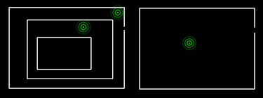
The preliminary search for contours is background and during its process you can specify the desired contours by clicking the mouse inside the contour. Selected contours are marked with green dots:
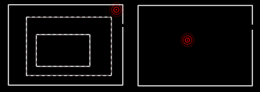
After contours precalculation is completed, the specified contours are selected for hatching and the points are erased. If there are breaks in the contours greater than the Gap tolerance parameter, the point indicator turns red:
A message is displayed suggesting solutions to the detected problem:
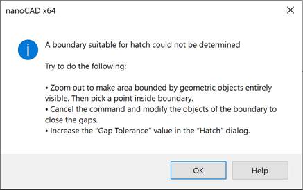
To deselect the problematic contours, click OK and click on the red dot again.
After a preliminary search, the found contours are highlighted in green under the cursor:
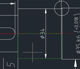
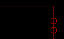
If you hover the cursor over contours with an allowable gap value (the value of the Gap Tolerance field) – red. In this case, the locations of the gaps in the contour are outlined in red circles:
If you are satisfied with the highlighted contour, you need to mark it by clicking the left mouse button to add it to the set of contours for hatching.
The highlighting of contours added to the set under the mouse cursor turns pink.
It should be taken into account that the operation of preliminary search for contours was performed only for contours that were completely displayed in the viewport at the time of clicking the Add: Pick point button. Therefore, if after clicking this button the drawing area was moved or the view was scaled (zoomed), the search process will begin again.
If, before starting the process of specifying points inside contours, the Precalculate contours checkbox was not selected, then the contours under the cursor will not be highlighted, since the process of recognizing all contours in the current view will not be carried out in advance. However, the process of specifying contours may take longer because each time you click the mouse, an attempt will be made to recognize a closed contour.
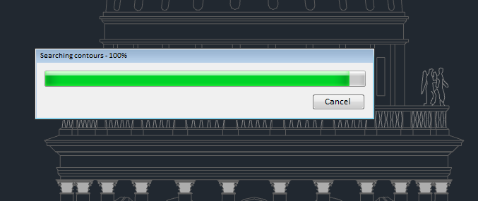
If it takes time to recognize the contour, a window with a progress bar will appear.
To exclude a contour that has already been selected, select it again by clicking the mouse.
If for some reason the selection results are not completely satisfactory, press ESC or select the Cancel command in the context menu to cancel the selected contours and return to the Hatch dialog to re-set the selection. The Preview and OK buttons in the dialog that opens will be disabled in this case.
To finish adding contours to the set, press ENTER or select the Enter command in the context menu to return to the Hatch dialog. Upon returning to the dialog, to preview the hatching result, click the Preview button. To complete the command without preview, click OK.
2.b Selecting hatch areas by specifying the objects that form the hatch areas
Click the Add: Pick point button and select the objects that bound the areas to be hatched.
To exclude an object from the selection, click on it again.
If the selection results are not completely satisfactory for any reason, press ESC or select the Cancel command in the context menu to cancel the selected objects and return to the Hatch dialog to re-set the selection. The Preview and OK buttons in the dialog that opens will be disabled in this case.
To finish adding objects to the set, press ENTER or select the Enter command in the context menu to return to the Hatch dialog. Upon returning to the dialog, to preview the hatching result, click the Preview button. To complete the command without preview, click OK.
When you preview the hatch result:
1. If the preview of the hatch is satisfactory, click Accept in the command line or click Enter or Accept in the context menu to finish the command. Pressing ENTER also finishes the command.
2. If the preview is not satisfactory, select Reject in the command line or click Cancel or Reject in the context menu to return to the dialog box and change the hatch options. Pressing ESC also returns to the dialog box.
To create the hatch using the inherited properties of a selected hatch:
1. Click the  Inherit properties icon. The Hatch dialog box closes temporarily, to select the prototype hatch.
2. Select the hatch object whose properties you want the hatch to inherit. The Preview and OK buttons in the opened dialog box will be blocked.
3. After selection, you can right-click in the drawing area and use the options on the context menu to switch between the Pick Internal Point and Select Objects options to create boundaries.
4. The order of the rest of the actions corresponds to the order of actions performed when you create a hatch.