
 De
De  Es
Es  Fr
Fr  Pt
Pt 

3D Solid Modeling Features
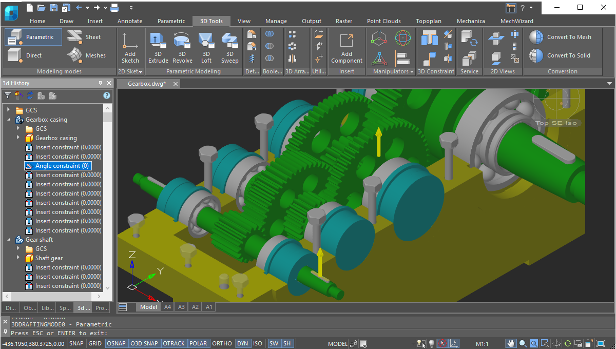
3D constraints
nanoCAD’s 3D constraints impose dependencies on geometry, mostly commonly to assemble parts into a single model. Using these tools, engineers create complex 3D assemblies by linking 3D objects. There are five 3D constraints available: Mate, Insert, Angle, Tangent, Symmetry. Constraints for every part are displayed by the 3D History Tree.
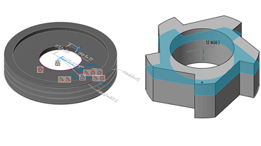
Parametric 3D solid modeling
nanoCAD’s parametric modeling mode allows engineers to build up 3D geometry, piece by piece. This approach to design is common among most MCAD applications, including SolidWorks and Inventor. As 2D sketches are turned into 3D features, engineers document their design intent through constraints and geometric relationships. As each step must follow the series of preceding steps, the parametric approach tends to require careful pre-planning. The history of the model’s construction is recorded by the history tree, which, in nanoCAD, is an Inspector panel with its own set of tools.
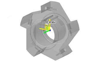
Direct 3D modeling
nanoCAD’s direct modeling offers a what-you-see-is-what-you-get approach, in which designers edit 3D models by pushing and pulling faces and edges. The primary benefit to direct modeling is the ease with which designs are altered, allowing rapid iteration and prototyping.
Natural 3D modeling UI
nanoCAD displays commands in groups for each type of modeling it offers: parametric, direct, sheet metal, and meshing. For example, while in parametric modeling mode, commands for creating 3D geometry based on parametric sketches are displayed; upon switching to mesh modeling, commands for creating 3D surfaces become available.
Commands that apply to all forms of modeling are always displayed on the ribbon, such as chamfers and rounds, Boolean operations, and construction geometry.
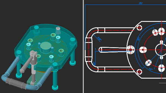
Associativity of 3D models and drawings
The associative relationship of models and their projections allows users to concentrate on designing in a 3D environment, paying attention to 2D graphics mainly for drawing design. All changes to the 3D model at any time will be displayed in the drawings, and the design elements made in 2D graphics will also correspond to these changes.
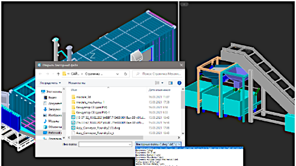
Model exchange via Import/Export
Models created using 3D Module can be exchanged with most CAD systems, exported to 3D printers, CNC machines and web-based viewers. Supported formats are:
- STL for stereolithography;
- Parasolid X_T, X_B for NX, Solid Edge, SolidWorks;
- JT, IGES, STEP - standard engineering data exchange formats;
- SAT, C3D - ACIS and C3D modellers' formats;
- VRML for 3D graphics on the web;
- COLLADA for interactive 3D applications.
Bounding prisms
nanoCAD uses 3D clipping to show the insides of models and to isolate parts. Each model space viewport can hold a bounding prism, a volume in 3D space outside of which drawing elements are not displayed. Prisms can be edited, deleted, and disabled. When disabled, elements outside the prism again become visible; disabled prisms are stored in the drawing so that they can be switched on again later.
External references
nanoCAD links external references inside assembly drawings to parts stored in external drawing files. Changes made by other design programs to external references are tracked and reported by bubble notifications.
3D navigation tools
nanoCAD provides interactive 3D navigation tools with which to display and navigate around 3D objects. Users have access to on-screen controls to change shading modes and rotate viewpoints in real-time. The controls operate quickly, even with large BIM models, massive point clouds, and complex 3D solids in a single drawing.
More great features
Semi-transparency for edited 3D objects
nanoCAD makes 3D objects semi-transparent during editing to make it easier to see and position them in space. The visual effect is available during the Move and 3dMove, Rotate and 3dRotate, Scale, Stretch, and Mirror commands, as well as while editing 3D objects with grips, and during commands that involve dragging and dropping.
Light sources
In model space with visual styles that support shading, the model is illuminated with one or two light sources behind the viewer and moves with the viewpoint, so that objects are always clearly highlighted. In addition, users can define custom light sources based on the properties of point lights, spot lights, web lights, and a distant light.
Point cloud formats
nanoCAD opens, displays, and edits 3D point cloud files captured by laser scanners in LAS, BIN, PTS, PTX, PCD, and XYZ formats.