De
De  Es
Es  Fr
Fr 

-
-
-
-
-
-
-
-
-
-
-
-
-
-
-
-
-
-
-
-
-
-
-
Creating Block Attributes
-
-
-
-
-
-
-
-
-
-
-
-
-
-
-
-
-
-
-
-
-
-
-
-
-
-
-
-
-
-
Creating Block Attributes
 Ribbon: Insert – Block Definition >
  Define Attributes
Menu: Home – Block >  Define Attributes
Menu: Draw – Block >  Define attributes…
Panel: Draw –
 Command line: ATT, ATTDEF
To define attribute parameters, open the Attribute definition dialog box.
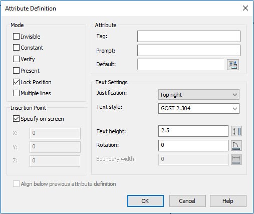
Options:
Mode
|
Invisible |
Turns on the mode at which the attribute value is not displayed on the screen and is not printed out. |
|
Constant |
Turns on the mode that assigns a fixed value for the attribute for all block references. When inserting a block with the attribute having a constant value, this value is not requested. If the attribute has a variable value, this value is not requested during the block insertion. |
|
Verify |
Turns on the mode of verifying the attribute value during the block insertion. |
|
Preset |
Turns on the mode that assigns the default value to the attribute during the block insertion. |
|
Lock position |
Turns on the mode that locks the location of the attribute within the block reference. When the mode is unlocked, the attribute can be moved relative to the rest of the block using grip editing. |
|
Multiple lines |
Turns on the mode that creates the value of attribute containing multiple lines of text. When the mode is unlocked, the filed for text entry is active for the By default parameter. When the mode is turned on, text entry field is blocked, the button |
 and the
 Attribute
|
Tag: |
Defines the attribute name. The name can consist of any characters except spaces. |
|
Prompt: |
Field to enter the prompt text displayed at request of the attribute value while inserting the block containing this attribute. If the field is empty, the attribute tag is used as a prompt. When the Constant mode is enabled, the field is blocked. |
|
Default: |
Field to enter the default attribute value. The field can be empty. |
|
|
Opens the Field dialog box to insert the field with a default value. The field is automatically updated with changes of value associated with it. |

Insertion point
|
Specify On Screen |
After the dialog box is closed, it will be proposed to specify on the screen the attribute insertion point in the block. |
|
X: Y: Z: |
Accurate coordinates of the attribute insertion point by three axes. |
Text settings
|
Justification: |
Drop-down list to select the type of justification of the attribute text. |
|
Text style: |
Drop-down list to select the text style. |
|
Text height: |
Field to enter the text height. |
|
Rotation: |
Field to enter the rotation angle of the text. For Fit in and By width align options for single-line attribute the Rotation option is not available. |
|
|
Buttons that temporary close the dialog box to specify on the screen by mouse cursor the text height, text rotation angle or boundary width for multiple-line attribute. |
|
Boundary width |
Specifies the maximum value of lines length in a multiple-line attribute, at exceeding which the text is automatically wrapped to another line. When the value is 0, there is no restriction on the length of a line. The option is not available for creating single-line attributes. |
|
Align below previous attribute definition |
Ensures placement of this attribute tag directly below the previous attribute tag. When the flag is checked, the text options of the current attribute will be fully copied from the previous attribute. This option is not available at the first attribute definition. |

To create a multiple-line attribute:
1. In the Attribute definition dialog box, to check the Multiple lines flag.
2. Define the attribute name, prompt, insertion point, modes and text options.
3. If necessary, enter the value in the Boundary width field.
4. Click the button  to open the context editor to specify the format of multiple-line attribute in the drawing.
5. Specify the left upper position of the multiple-line attribute in the drawing.
6. After the text entry is completed, click OK button in the Text format dialog box to return to the Attribute definition dialog box.
7. Click OK to close the Attribute definition dialog box.
8. Specify the attribute insertion point in the drawing (if the Specify On Screen is checked for the insertion point).
After the attribute is created, it can be included in the set of objects in creating a block, i.e. in response to the query on objects selection in creating a block, it is necessary to select not only geometric objects, but also attributes. The attributes selection procedure determines the order of queries on entering attribute values when inserting the block.
It is also possible to associate the attribute with the block during the block redefinition.
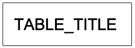
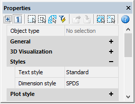
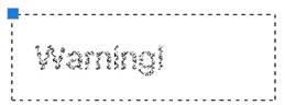
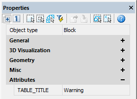
Example of the “Table_title” attribute meaning “WARNING” (plate view and information displayed in Properties box):
|
Before the attribute insertion in the block |
After the attribute insertion in the block |
|
|
|