
 De
De 

WORKING WITH STANDARD ELEMENTS
Parts Library nanoCAD Mechanica23 is a database and stored in a file with the extension * .mcs. By default, after installing nanoCAD Mechanica23 used base recorded in a file in the folder std.mcs data, housed in the installation directory of the program nanoCAD Mechanica23.
Select another database possible, specifying the desired file in the "Database access"option in the settingsnanoCAD Mechanica23 "The path to the local database".
Parts of the database can be exported as individual files, or import from external files into the current database of standard elements.
The basic tools for working with database objects
The basic tools for working with database objects are:
"Main menu - Mechanica - Standard parts"
or on the toolbar "Standard parts"

· Markers, Groups
· Cover
·  Move up
·  Regenerate supression contours
· Part trim
·  Add view
 Main menu: Mechanical - Standard parts -
  Tab manager.
Ribbon: Mechanical - Standard parts - Tab manager.
Toolbar: Tab manager (on toolbar "Standard parts").
 Command line: MCTABS.
Object Manager nanoCAD Mechanica 23 includes the following tools:
· Manager database of standard objects
· Objects
· Pruning of standard parts
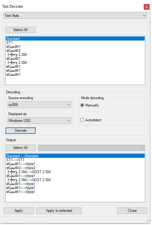
· Finding and replacing text
· Copying properties
Tab "Library" object manager is a universal means of access to the standard database objectsnanoCAD Mechanica23.
Details in the database are classified according to their design purpose.

Management and structure the database by using the toolbar and the context menu that includes the ability to add, delete, or rename folders.
·  Del object. Removes the selected item or folder from the database
·  Add folder. Adds a folder to the database
·  Insert object. Performs insert the selected database object in the drawing
·  View. Includes preview of database objects
·  Search panel. It includes search bar facilities on base
·  Refresh. Updates the tree base in the object manager. Press this button after making changes to the database
The context menu has a different structure depending on call.
In the palette - the object context menu:

In the palette - the context menu of a folder:

"Add Folder" - adds the folder to a dedicated subsidiary. If the command was run on the selected object, the folder will be added to the parent folder object.
"Save object in database as dwf block" - This utility allows you to save a single database of the drawings in format dwg, including standard items nanoCAD Mechanica23, design elements and primitives nanoCAD.
"Delete object" - This command deletes the selected object.
"Delete folder" - This command deletes the selected folder with all its contents.
"Rename" - The command allows you to rename an object (folder).
"Import object" - Adding to our previously exported file or folder object database DB.
To import a database from an external file, use the command "Import object" in the context menu invoked by a right-click on any folder or object in the section "Library" object manager. This will bring up a dialog box in which you specify the path to the file.
When importing compares the last modification date of the original (stored in the database) and the imported object. At concurrence of the imported content from content database objects will be updated only if they have more recent modification date.
If the command "Import object" was called for a standard lens, the outer fragment is imported to the folder containing the object.

"Export object" - Save the file to disk or folder object database DB.
To export any portion of the database you should use the command "Export object". In the resulting dialog box, then you need to specify the path and file name for saving the captured designated section base.
|
Note: |
Import operation into the database or export from the database can be made as separate objects, and entire folders with libraries of parts. |
"Send by email" - It creates an e-mail with an attachment - Export objects.

"Copy" - Stored in a buffer object reference to paste a label on it.
"Paste shortcut" - Inserts a shortcut to a previously copied object
"Open with ScriptMaster" - Opens the object in the Object Wizard to edit.
"Add this folder palette" create a bookmark in the palette manager of the objects of the selected folder.
"Refresh" - Updating of the database (for example, after editing).
Tab "Objects" object manager is a universal means of reviewing, monitoring, editing facilities nanoCAD Mechanica23, are on the drawing.
Places on this tab are grouped into sections - for example, standard parts, callout, bolted connections, etc. In order to navigate in the drawing the selected object is highlighted.

·  Edit object.It calls the dialog for editing the selected object
· Del object. Deletes the selected object
· Refresh. Updates the list of objects. The button is used when adding or removing objects from the drawing
·  sQuick select. Search Tool nanoCAD Mechanica23 objects in the drawing on the set parameters, run the command "Quick Pick"
·  Find and Replace. Open dialog boxFind and Replace.
In addition to the teams that are in the toolbar, the context menu of a selected object contains the following items depending on the selected object, and includes a team of repeating the context menu of the object on the drawing. Thus the tab "Objects" allows you to edit objects without having to search for them saturated drawing regardless of layer.

For example, for sub-database nanoCAD Mechanica23, further include items "Change representation", "Bring to Front", "Send to Back", and "Change cover mode".
Option "Hide" makes the selected object invisible in the drawing.
Main menu: Mechanical - Standard objects - Standard parts library.
Ribbon: Mechanical - Library - Standard parts library.
Toolbar: "Standard objects") - Standard parts library .
Command line: MCSTD.
Inserting standard parts from the nanoCAD Mechanica 23 database is carried out using the database manager, which can be presented in full (dialog) form and in the form of a tool palette.

1. Select the insert object.
2. After selecting the object, specify the insertion point for the object.
3. Select the insertion direction (not all parts need to specify a direction vector). The dialog box for selecting object parameters will open.
4. Adjust the options in the dialog box.
The standard dialog contains the following sections (sections are divided into tabs):
|
Important! |
The composition of the sections (tabs of the insert dialog) is determined by the class of the part, its parameters and the environment of the insert. |
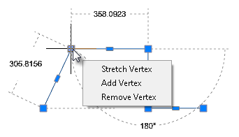
The button  "Dynamic input" turns on the mode of visual definition of parameters when inserting.

As you move the mouse cursor, follow the change in the size of the object. LMB click to confirm the selection of the parameter value.
The "Apply" button allows you to apply the selected parameter values to the object without closing the dialog box. This deactivates the "Dynamic input" mode.
|
Important! |
The description given here refers to the standard dialog for selecting parameters. Some objects of the nanoCAD Mechanica 23 base use special dialog boxes. In special dialog boxes, the location of the controls may vary. |
|
Note: |
If the path to the custom help is specified in the "Help" parameter of the standard part form, it will be called if the focus is on the form control. If the focus is on the "Cancel" or "OK" buttons, the help for standard items opens. |
5. Click "OK" to complete the dialog.
· Add folder - Adds a folder at the specified location in the object tree.
· Delete - Deletes the selected object or folder.
· Edit note - Changes the name and note of the selected object.

· Import - Imports a base object.
· Export - Exports a base object.
· Send by email - Exports the object and sends it to the specified mail address.
· Cut - Cuts an object, folder.
· Paste - Inserts a previously cut object, folder.
· Paste shortcut - Inserts a shortcut to a previously cut object, folder.
· Add folder - Adds a folder at the specified location in the object tree.
· Delete - Deletes the selected object or folder.
· Edit note - Changes the name and note of the selected object.
· Publish- Makes the object visible to other users of the network database. Objects can be published by administrators and editors (editors only their own objects).
· Remove publish - Makes the object invisible to other users of the network database. Objects can be unpublished byadministrators and editors (editors only their own objects).
|
Note: |
The "Publish" and "Remove publish" commands are only available to editors and database administrators. |
On the "table settings" dialog insert standard parts displayed parameters responsible for the geometry of the object. These parameters correspond GOST'u (OST'u).

Properties of the parts that can be changed and described in the script are displayed on the "Properties". On this tab located custom and reference parameters, switches species details and details of performances.

In the process of inserting parts "Glass" automatically set the relationship between the items "Bearing", "End caps" and "Glass" (with parts falling into the aperture).
For items that have parameters available for manual entry or dynamically change tab "Properties" presents additional opportunities.
Consider the example of the detail "Glass" features interaction details.

The "Bearing diameter" - gray. This says that this option is not available for editing and dependence associated with the diameter of the bearing.

To enable editing of this option, you must go to the tab "Dependencies" and remove the dependency between the diameter of the items "Bearing" and an inner diameter of workpiece "glass.".
Remove Dependency pressing the "Delete"
After this option is available for editing.

The "Dependences" tab allows editing of dependences set automatically during the details allocation on the drawing, and dependences set with the "Dependences control dialog" .
Types of dependencies:

Parametric - settable parameter object equality arithmetic expression object parameters, which occurs accession.
For rod attachment parts provided estimation during insertion. The result of the calculation is the recommended thread diameter for given loading conditions and strength class details.
For some types of rolling bearings estimation is also provided. The result of the calculation is the life of the bearing for the given loading conditions.
Main menu: Mechanical - Standard parts -  Reinsert object.
Ribbon: Mechanical - Standard parts - Reinsert object.
Toolbar: Reinsert object (on toolbar "Standard parts").
Command line: MCPICKPOINT.
Serves to re-insert the object in the drawing, combines editing commands properties and movement of item.
1. Click reinsert object.
2. Select the drawing or pasted object from the database.
3. Specify the new position of the object and insertion point.
4. Click OK.
Working with groups in Construction 23 is performed using the following commands:
Main menu: Mechanical - Standard parts - Markers, Groups -  Group objects.
Ribbon: Mechanical - Library - Group objects.
Toolbar: Group objects ( "Standard parts").
Command line: MCGROUPOBJECTS.
Constraints describing the interaction of two or more objects, It is advisable to store these in the objects database in a related group. Group nanoCAD Mechanica 23 has the following features:
· Group is stored in the object database, has a pattern preview before pasting.
· Components of the group in addition to objects nanoCAD Mechanica 23 can be primitives and blocks in nanoCAD.
· Group may be transferred as part of the database file to other users.
· Group may have additional dependencies with other groups and objects.
· Components of the group remain together parametric dependence.
· Components in the group can be specified both individually and in groups.
Thus, the group is a powerful way of organizing and structuring graphics data in a separate local file drawing document.
Button  Group objects
Gather and create database objects in the design position in the drawing. On the toolbar, Library objects,click Group objects.
Select the required objects in the drawing AutoCAD specify the origin of the group.
In the dialog box New group on the left side is a list of objects in the group. Name objects in the list is taken from the string value for the specifications set in the properties of objects.
Button  Highlight group objects highlights and centers on the screen objects in the group.
Button  Set parameter table. Opens the editor table settings. Table of parameters used to select the group attribute values from a predefined list of values.
Button  Show form editor. Opens Form Editor to create a special dialog box.
Button save changes to database. Saves the base group Construction Site 23.
In the right part of the window picture preview and a list of attributes for the group.
Editing attributes produced in the cells of the table.

Adding attributes produced from the parameter list of objects in the group.
Expand the selected entry in the list (with the "+" next to the name of the object) and double click on the parameter, add an attribute in the table.
You can install a bidirectional relationship between the group and attribute parameter object that is associated with this attribute. The list of attributes in the column Attribute Properties , click the left mouse button on the icon  . Depending on the mode change bidirectional, it will indicate the icon
  . Thus, when the value of the attribute group, and the parameter of the object is changed.
Save the group of objects in the database by pressing the buttonsave changes to database. Choose a location and name for the group (the default group name matches the specified value attribute Group Name). Click OK.
Group created and saved to the database. Now you can insert multiple grouped objects in a drawing, resizing and positioning of objects, while preserving established parametric and geometric constraints.
|
Important! |
Group objects only retains information about dependencies between objects and attributes set. For insertion to be carried out correctly, you must have a database of all the objects in this group. |
When working with a group of attributes of the various available methods for selecting values. In the context menu of the column Properties attribute in the attribute list, select:

· Add property from object - allows you to set the attribute value by linking it with an attribute value of another object in the drawing.
· Set to unique string - allows you to set the attribute-counter, which will increase its value by 1 for each subsequent inserted marker. In the Value column for the visible attribute counter must specify a character string - prefix. The drawing will be appended to the prefix value of the counter.
· Set to calculated field - allows you to set the attribute value using a mathematical expression, using references to other attributes of the marker and mathematical functions. In reference to another attribute marker use the name of the attribute recorded in braces.
· Automatically increment - allows you to set the attribute-counter, which will increase its value to 1, compared with the same attribute of the previous insertion marker. This attribute allows the counter-repetition of identical values for several markers that distinguishes it from the attribute set to a unique value.
· Set to simple field - sets the attribute type by default.
Insert group may be carried out as the object manager , and with a tool insert group.
Button  Insert Group toolbar Library objects opens a dialog Box group.
In the list of the group and press OK. If you insert a group of objects , you must specify the insertion point of the group. If you insert a group of dependencies , you need to select the drawing objects that you want to associate with the dependencies.
In the dialog box Insert group commands are available:
 Create group. Creates a new group.
 Delete group. Deletes the selected group from the database.
 Select items from the drawing for the group. Used to edit an existing or new group.
 Detail groups. Opens a list of groups of items.
 Dependence group. Opens a list of groups dependencies.
Switch multiple . Enables insertion of multiple groups in the drawing.
Switch Add group marker. If installed, together with a group of drawing a marker is added to the group.
Marker group is designed for group editing and data to other objects in the drawing (see Binding arbitrary graphical and tabular data ).

After you insert a group of objects in the drawing, or when the command to edit the marker group opens the edit dialog group.
 Highlight group objects. Highlights and centers on the screen objects in the group.
 Edit marker Properties. Includes editing mode, where you can change the set of objects in the group, add or remove attributes.
 Object tree. Enables and disables the object tree in the left pane.
Set parameters table. This button is available if the group contains a table of parameters. In the dialog box, select the row attribute values, and click OK.
Group dependencies remain parametric description and assembly relationships between objects. When you insert such groups they are not added to the drawing objects, but only established the relationship between existing objects.
Consider creating and maintaining relationships between the two cuffs.
|
Important! |
Before you create a group, you must place the drawing objects to be included in the group and set the dependencies between objects. |
Insert the base of the two objects Cuff GOST 8752-79. Set between the geometric co-directional dependence Combining axis and the plane at a distance obj.B (see Constraints between two objects ) and the parametric dependence of the outer diameter.

Select Insert group.
In the dialog box, click Dependence groups.

Button Creates group. In the groups list, change the name of the new group (eg, "Package cuffs"). To edit, click the left mouse button on the name of the group.

Click Select group details from drawing and select the drawing both cuffs. Press Enter.
In the dialog box, select the dependent listed in the list established between objects. Click OK.

Look at the result of the creation of group dependencies.

In the description of the group under the picture preview Set the selection order when inserting objects group dependencies.
Group dependencies are stored in the database automatically. Click Cancel to complete the group.
Insert a drawing of the base of the cuff, which must be applied to create a dependency.

Select Insert group , click Group Dependency . In the list of dependence " Package cuffs. " Click OK.
Select the drawing cuffs to be connected sequentially (in the example need to perform steps 10-11 twice).

Automatically set dependence stored in the description of the group.
Main menu: Mechanical - Standard parts - Markers, Groups -  Insert group.
Ribbon: Mechanical - Library - Insert group.
Toolbar: Insert group ( "Standard parts").
Command line: MCINSERTGROUP.
 Library: Groups.
Insert group Box lets you create a set of objects with superimposed parametric and geometric constraints.

 Create group
 Deleting Group
 Select group details from drawing

 Switch between groups of objects and dependencies
The mechanism used in the team group insert , you can insert a group of objects

The "Add marker group" enables the group a graphic element - a marker located at the insertion point of the group. In marker may include parameters of individual parts group that can help you when pasting automatically change the geometry of the group of related components.
"Multiple insert" allows you to create multiple copies of the selected group.
If a user group has been maintained by the standard in the folder $\MCS\Groups, then insert it in the tree by choosing the object manager.
If a group is defined form, then insert dialogue is as follows:

· The dialog box includes a tree of groups - a list of objects and their parameters group. This tree can disable button 
· The preview window group
· Form input values group
When you click on you can switch to edit mode group settings.
Main menu: Mechanical - Standard objects - Markers, groups -  Add marker.
Ribbon: Mechanical - Library - Add marker.
Toolbar: "Standard objects"- Add marker.
Command line: MCCREATEUMARKER.
The "Marker" tool is designed specifically to create a connection between an arbitrary graphic object (primitive) nanoCAD and a spreadsheet-specification. A universal marker is a translator of data from drawing objects into the nanoCAD Mechanica 23table by means of special means - marker attributes.
Marker attributes can be visible or hidden. The values of the visible attributes are displayed in the drawing as text strings.
The marker, as an object nanoCAD Mechanica 23, can be saved in the object library and used repeatedly. The marker can also be included in the groups of objects nanoCAD Mechanica 23, providing the ability to specify the entire functional groups.
Let's consider creating a marker in the form of a positional leader.
1. Set the required current scale.
2. Insert two text lines into the drawing and draw a horizontal line between them.

These objects will form a leader shelf template with two text labels. To use text strings as marker attributes, the first character must be "$".
3. Call the command "Add marker", use a box or crossing box to select the objects that made up the marker.

4. Snap the base point of the marker.

5. The "Creation of a marker" dialog box appears. The properties table will list the attributes entered in the callout text boxes:

Column "Name" contains the working name of the attribute.
Column "Description" describes the attribute.
In column "Value" the values of the attribute are entered. Values can be either numeric or text. Auxiliary commands are available in the context menu of the "Value" column.

Column "Attribute property" is used to indicate the type of the input attribute. Various attribute labels are provided to indicate their type. The default is "Set to simple field".

Attribute types:
· Add property from object- allows you to set an attribute value by associating it with the attribute value of another object in the drawing.
|
Important! |
An object is understood as an object from the base of standard products. |
After choosing the type, it is suggested to select the object and the object attribute.

After selecting an attribute, its value falls into the "Value" column, and in the "Attribute property" column the name of the selected attribute.

After assigning an attribute, you can change the type of relationship with an object attribute:
 One-way communication - changing the value in an attribute of an object affects the value of the marker.
 Two way communication - changing the value in the marker affects the attribute of the object, and vice versa.
 Basic communication - an attribute of an object can only be changed from a marker. If the attribute is a table value in a basic relationship, the closest value from the table is displayed. The entered value will be displayed in brackets.
· Set To Unique string - allows you to set a counter attribute that will increase its value by 1 for each subsequent inserted marker. In the "Value" column for the visible counter attribute, you can specify a character string - a prefix. In the drawing, the counter value will be appended to the prefix.


· Set to calculated field- allows you to set the value of an attribute using a mathematical expression, using references to other marker attributes, operators, and mathematical functions. The name of the desired attribute is used as a reference to another marker attribute.
|
Note: |
Computed attributes are defined and calculated from top to bottom. |
|
Important! |
Calculations are performed in curly braces. |
Function:

Result:

· Automatically increment - allows you to set a counter attribute that will increase its value by 1 compared to the same attribute of the previous inserted marker. Such a counter attribute allows repetition of the same values for several markers, which distinguishes it from an attribute set to a unique value.
· Set to simple field - sets the default attribute type to plain text.
|
Note: |
Attributes included in the block can be included in the marker attribute table nanoCAD! |
6. Edit the marker using the marker controls at the bottom of the dialog box.

Include:
· "Marker draw mode". When you click on this button, a drop-down list of rendering modes appears:
·  Simple marker.
·  Draw position line.
·  Linear align.
When you select the display method with the addition of a leader line, an additional button  "Arrow Type" appears to select the type of arrow:

Click this button and select the desired extension line arrow type.
Arrow display parameters are defined in the "Settings - Symbols - Extension - Additional extension lines" settings.
·  "Unploted". When this button is enabled, the marker is placed on a special layer that is not displayed when printing. When this mode is activated, the icon on the (
 ) button changes and the marker is displayed in gray on the screen (in accordance with the color of the non-printed layer).
·  "Show form editor"- calls the custom form editor to create a dialog for working with marker attributes.
The following commands are available in the drop-down menu:
"Edit Form". Open Form Editor.
"Add Form. Adds additional forms, while the marker can change the appearance of the form, by condition or by the user's choice. By default, the marker has one form.

The form editor uses standard Windows form generation technology. The toolkit consists of three blocks - the graphic editor area, the toolbar with form objects and the properties window of the inserted elements. For inserted fields, the "Field Name" ("Variable") can be selected from the list of existing marker description fields. In this case, the default field value is equal to the field value in the marker description.
When adding a second form, you are prompted to enter a name for the form. The variable Tag - mcFormName is added to the properties table. This variable is responsible for the name of the form, it can be set in a calculated field and, for example, made equal to execution. Empty or "Main" is considered the main form.

·  "Geometry". Used to change the appearance of the generic marker and define the insertion point.
The following commands are available in the drop-down menu:
Get new geometry. The button is used to change the appearance of the universal marker and define the insertion point.
Export marker source graphics. Exports marker geometry to a file.
Add Implemetnation. Adds additional performances, while the marker can change its appearance, by condition or by the user's choice.
When creating a new implementation, you are prompted to enter its name. When adding implementation, the Tag - mcImplementation variable is added to the properties table. This variable is responsible for the name of the current marker implementation. It can be set to a calculated field or linked to a list on a form. Empty or "Main" is considered the main implementation.
·  "Set parameters table". Opens the marker parameter table editor. When inserting a marker and having a table of values, it is possible to assign a group of values to the marker attributes.

In the list, select the parameters whose values will be selected from the table. In the right part of the window, enter the required number of lines with values. Close the dialog with the "OK" button.
·  Save changes to odatabase. The button is intended for writing a marker to library nanoCAD Mechanica 23.
·  Apply changes to all markers of this types. Applies changes to all markers of this type in the drawing. Serves for changing the marker template for all markers made according to this template and inserted into the drawing.
7. If necessary, add any number of hidden attributes, filling in the rows of the table in sequence. The attribute is added in the bottom line of the table, marked with an "*" symbol.
8. For future use of the marker, save it to the database as a named object.

In the "Create element" dialog box, specify the path to save, the name of the object and the note (for more information on working with the object base, see the nanoCAD Mechanica 23Object Manager). After you save the marker, a message appears prompting you to update the existing copies of the marker in the drawing.
9. nanoCAD Mechanica 23 makes it possible to immediately apply the created marker. The command line prompts you to install the generated token. Pick an insertion point in the drawing. Identical markers can be simply copied in the future. In other cases, the marker is inserted directly from the base.

Editing of a marker is carried out in a dialog box, the title of which corresponds to the name of the marker. For example, when you call for editing the "Position_Marker" marker, the creation of which was described in the previous paragraph, the dialog box will look like this:
Additional commands are located at the bottom of the window:
· "Marker draw mode". When you click on this button, a drop-down list of rendering modes appears:
· Simple marker.
· Draw position line.
· Linear align.
When you select the display method with the addition of a leader line, an additional button "Arrow Type" appears to select the type of arrow:
Click this button and select the desired extension line arrow type.
Arrow display parameters are defined in the "Settings - Symbols - Extension - Additional extension lines" settings.
· "Unploted". When this button is enabled, the marker is placed on a special layer that is not displayed when printing. When this mode is activated, the icon on the () button changes and the marker is displayed in gray on the screen (in accordance with the color of the non-printed layer).
·  "Highlight info source object". Highlights in the drawing the object with which the marker is associated (The function is available if the "Add property from object" mode is set for one or several attributes and the corresponding object was specified when inserting the marker).
·  "Edit marker properties". Turns on the edit mode, in which you can change the appearance of the marker, add or remove attributes.
mcImplementation - Execution management. Empty or "Main" means the main view.
mcFormName - Form management. Empty or "Main" means the main form.
mcArrowSize - Arrow size control.
mcDefLayer - Controls the marker location layer. The "Value" field contains the name of the layer.
mcShowFormOnInsert - Controls the display of the dialog when inserting. If the value is 0, the dialog is not shown when inserting. The value can be calculated.
Main menu: Mechanical - Standard parts - Markers, Groups -  Template wizard.
Ribbon: Mechanical - Library - Template wizard.
Toolbar: Template wizard ( "Standard parts").
Command line: MCTWIZ.
Template Wizard is designed to create easy to use tools of commonly used design elements drawing.
When the command will be asked to select an object to create a template. If the object was preselected, then immediately start dialogue Template Wizard.
Button Create template - creates a template in the database or applies the changes made in the editor.
Button From - Starts the form template.
Button  Create a new template - Creates a new template in the database based on the selected graphics and created form.
Button  Delete form - deletes the created form template.
Example of creating a template
Consider the example of creating a template signs of roughness. To do this, the drawing shall bear one designation:
After you run the Wizard Templates chosen designation roughness.
To work with the template you must save it in the database that will be invited to do by pressing the button  .
.

Then click on the Create a form and create a form using the notation tools online forms.
For example, we can take two parameters - the first line designations and direction of irregularities. Both parameters are added to the form as a combo box (drag while holding Ctrl).
 >
> 
After editing, we obtain the form of the following form:

Close the form editor, click to update in template.

Template will be saved in the database and will be displayed in the object manager.

Now when you insert from the database will be able to also place the designation of roughness on the shelf line-outs, but when you edit your form will appear:

If the original graphics selected block nanoCAD, its attributes are also displayed in the form editor as available variables.
 >
> 
When creating a form in the database and maintaining such a block is inserted into the drawing as a block of the same source, only the attributes can be set up via a custom form.

Main menu: Mechanical - Standard parts- Cover -  Change hidden mode.
Toolbar: "Standard parts" - Change hidden mode.
Command line: MCCHCOVER.
The command switches the display mode of hidden lines.
nanoCAD Mechanica 23 allows you to hide individual graphics elements. The overlapping nature of the base object or user block is determined by a special parameter - the overlap level ZOrder. ZOrder - this is a numeric parameter whose value determines the overlap priority. An object with a large ZOrder value overrides an object with a lower value.
Primitives nanoCAD have the lowest overlapping level and therefore are always overlapped by objects from the database. That at an insertion of object nanoCAD Mechanica 23 objects nanoCAD did not overlap, it is necessary to disable the switch in the object insert dialog "Cover primitives":

The area in the drawing that the base object covers nanoCAD Mechanica 23, is called "Contour of suppression". An overlap exists within this contour.
1. Call command.

2. In the context menu, select the desired view of the overlapped objects "Normal", "Dotted" or "Switch".
|
Normal |
Dotted |
Switch |
|
|
|
The command appends the value. Those. If a normal overlap has been established, then the dashed line becomes, and vice versa. |
3. Select the secant frame for the objects for which you want to change the overlapping mode.
4. Repeat if necessary items 2 and 3, or complete the command on the key "Enter".
Regenerate suppression contours
Main menu: Mechanical - Standard parts - Cover - Regenerate suppression contours.
Toolbar: "Standard parts" - Regenerate suppression contours.
Command line: MCCOVER.
Regenerate the drawing and redraw the contents of the current viewport.
|
Before |
After |
|
|
|

Main menu: Mechanical - Standard parts - Cover - Move up.
Toolbar: "Standard parts" - Move up.
Command line: MCMOVEUP.
1. Call command;

2. Select the objects you want to move up;

3. Select the objects to be compared;

4. After the selection is complete, the objects that need to be moved up will automatically increase the overlap level (ZOrder).

Main menu: Mechanical - Standard parts - Cover -  Move down.
Toolbar: "Standard parts" - Move down.
Command line: MCMOVEDOWN.
1. Call command;
2. Select the objects you want to move down;
3. Select objects to be compared;
4. After the selection is complete, the objects that are to be moved down will automatically decrease the overlap level (ZOrder).
Main menu: Mechanical - Standard objects - Part Contour Trim -  Add part trim.
Ribbon: Mechanical - Library - Add part trim.
Toolbar: "Standard objects"- Add part trim.
Command line: MCTRIM.
The command allows you to trim objects of metal structures.
Trimming with contour indication
1. Call the command "Add part trim".
2. Pick an outline. A contour can be a line segment, circle, arc, polyline (closed and open).

3. Specify trimming objects.
If a circle or closed polyline is used as a path, the trimming object is selected within the path.


If a linear path is used, the trimming object is selected from one side of the path.


4. Press the "Esc" button to end trimming. The object will be trimmed.

1. Call the command "Add part trim".
2. Select trim mode "COntour".
3. Draw a closed polyline path.

4. Pick a trimming object within the path.

5. Trimming an object is made.

Trimming mode "rectangle by tWO points"
1. Call the command "Add part trim".
2. Select trim mode "rectangle by tWO points".
3. Pick the first corner.

4. Pick the second corner.

5. Pick a trimming object inside the rectangle.

6. Trimming an object is made.

Trimming mode "rectangle by thrEE points"
Allows for trimming at the desired angle.
1. Call the command "Add part trim".
2. Select trim mode "rectangle by thrEE points".
3. Pick the first point.

4. Pick the second point.

5. Pick the size of the outline.

6. Pick a trimming object inside the rectangle.

7. Trimming an object is made.

1. Call the command "Add part trim".
2. Select trim mode "HOle".
3. Pick the center of the hole.

4. Pick a radius for the hole.

5. Pick a trimming object inside the circle.

6. Trimming an object is made.

Main menu: Mechanical - Standard parts - Part Contour Trim -  Remove part trim.
Ribbon: Mechanical - Library - Remove part trim.
Toolbar: "Standard parts" - Remove part trim.
Command line: MCTRIMDELETE.
The command removes a previously created trim.
1. Call the command "Remove part trim".
2. Specify the objects you want to reset and press "Enter" (or press "Spacebar") to select all objects.

3. The specified objects will be restored to their original state.

Main menu: Mechanical - Standard parts - Add view.
Ribbon: Mechanical - Standard parts - Add view.
Toolbar: Add view (on toolbar "Standard parts").
Context menu: Add view (on select object).
Command line: MCADDVIEW.
Designed to quickly add a new type of projection from the base of the inserted object to the drawing.
· Select the object to copy.
· Specify the insertion point of the object. Context menu commands Front / left / right / top / bottom standard projection (to insert a particular projection, it is necessary that it be recognized in the object).
· Context menu commands Point, Angle mode selection switch, respectively the insertion point or selection mode direction.
· Complete the cyclic command.
Adding a projection view to the object database can be done using the Add View from the context menu for the selected object.
Main menu: Mechanical - Standard parts -  Change representation.
Ribbon: Mechanical - Standard parts - Change representation.
Toolbar: Change representation (on toolbar "Standard parts").
Context menu: Change representation (on select object).
Command line: MCCHANGEREPRESENT.
· Press the button and select the database object in the drawing.
· Context menu commands Full, Simplified select the object representation.
Switching presentation can be accomplished by using the Change view from the context menu for the selected object.
Main menu: Mechanical - Standard parts -  Mirrow part.
Ribbon: Mechanical - Standard parts - Mirrow part.
Toolbar: Mirrow part (on toolbar "Standard parts").
Command line: MCMIRROWSTD.
· Press the button and select the database object in the drawing.
· Press Enter.
Occur along the axis of revolution object X.
Main menu: Mechanical - Standard parts -  Regenerate Std Parts.
Toolbar: Regenerate Std Parts (on toolbar "Standard parts").
Command line: MCREGENSTD.
The team needed to upgrade the graphics part of the object (s).
1. Call the command "Regenerate STD parts"
2. Specify the objects that you need to update or Enter, if you need to update all of the objects.
3. These objects will be updated
Main menu: Mechanical - Standard parts -  User defined object.
Ribbon: Mechanical - Standard parts - User defined object.
Toolbar: User defined object (on toolbar "Standard parts").
Command line: MCCUSTOMOBJ.
Tool User object makes it easy to group in objects nanoCAD and nanoCAD Mechanica23 into a single object. Custom objects support the ability to overlap other objects in the drawing.
1. Select the objects to create a custom object.
2. Specify part origin point.
3. Specify the drawing insertion and direction.
4. In the dialog box, set the value of the level of overlap of the object (for Level Z).

When you create a custom object contour suppression, external contour of the object is automatically detected contour suppression external contour of the object. Subsequently, the control circuit is used when objects overlap on the drawing..
Custom objects support editing with standard tools nanoCAD Mechanica23.
Main menu: Mechanical - Standard parts -  Add constraint.
Ribbon: Mechanical - Library - Add constraint.
Toolbar: Add constraint ( "Standard parts").
Command line: MCCONSTRAINT.
In the dialog box Constraints:

In the dialog box set parametric and assembly (geometric) dependencies between database objects.
The window is divided into two parts:
Left - The child
Right - The parent object
Use  1-selected object and 2 were selected to the choice made in the drawing, respectively subsidiary and parent objects. After selecting an object in the corresponding half of the window, a list of parameters of the object, which includes:
· Property name
· List surfaces (work surfaces)
· The list object's parameters
· List of installed parametric relationships
· List of installed assembly constraints

On two tabs depending Parametric and Assembly constraints established relationship between parent and child objects.
Parametric dependence connects the parameters of objects.
Assembly dependence binds workplanes objects.
Button  New dependency. Allows you to create a new dependency
Button  Delete dependency. Deletes the selected list dependence
When adding or editing button is activated depending  Save dependence, which allows you to save your changes.
Installing the parametric dependence
When installing the parametric constraints is associated parameters are recorded in the corresponding input fields located below the list object's parameters. Selecting the link parameters by double-clicking on the corresponding parameters in the list.

Installing assembly according
To install the switch assembly according to the tab Assembly constraints.
Choose binding surface by double-clicking on the appropriate working plane from the list.

Selecting the plane can also be done visually in the drawing by clicking labelled plane and the linked marker indicating the working plane of the object.

The choice of method depends overlay using the buttons at the bottom:
 Axial and surface alignment
 Surface alignment
 Combination axis
 Direction
Choose mutual orientation related planes using the buttons:
 Counter-directional
 Codirectional
Button  Bidirectional constraint. Enables two-way relationship in which a related parameter or surface of the parent object changes with appropriate changes to the child object.
Main menu: Mechanical - Standard parts -  Connect objects.
Ribbon: Mechanical - Library - Connect objects.
Toolbar: Connect objects ( "Standard parts").
Command line: MCCONNECTTO.
This command is used to overlay preset assembly and parametric dependencies on objects in the drawing.
After running the command must specify.
1. Child object - an object that will be joining.
2. Parent object - the object to which you will attach the child object.
Upon completion of the command will be imposed on the details of parametric and geometric constraints defined in their script..
Main menu: Mechanical - Recognition -  Symbol block recognition.
Ribbon: Mechanical - Utilities - Symbol block recognition.
Toolbar: Symbol block recognition (on toolbar "Recognition").
Command line: MCRECS.
Using commands recognition of graphic objects will significantly speed up the process of registration as the projections of old drawings and new, but made by hand without the use of any application.
Character Recognition is offered to carry out automatic or semi-automatic mode.
nanoCAD Mechanica 23 recognizes the following symbols and signs on the drawing:
· ymbols, text callouts;
· formats;
· specification sheets;
· table.
By default, the toolbar "Character Recognition" is not displayed.
To invoke it, place the cursor pointer on the main toolbar nanoCAD Mechanica 23and click the right mouse button. In the context menu, click on "Recognition".
You will see an additional toolbar:

|
|
Character recognition |
|
|
Recognition formats |
|
|
Recognition specifications |
|
|
Table recognition |


To perform automatic recognition of characters in the drawing context menu after recognizing any symbol.
Automatic character recognition requires checking the entire drawing, so it is not recommended for use in saturated drawings.
Recognize the main frame with the inscription enough to the source drawing contained within the Standard size, two contour lines and the title block.
Entries in the title block recognizable drawing are automatically entered in the dialog box title block, add additional fields and zones.
Recognition forms specifications
Information in the figure, placed on the forms specifications after recognizing transferred to Excel.
For correct recognition itself form the specification may be a block or drawn objects such as "Line".
The text in the cells of the form specification - an object of type "text".
Shortcut: ALT+RBM (when you hover over a line or shading standard element).
It overrides the style of the individual lines in a standard cell.
1. Insert a standard element, such as I-beams.In the properties, select the rendition of "left view" and the type of display "view with a cut".

2. Do not get fooled by the hatch and press ALT+RBM. The "Overrides" dialog box.

Colour -changes the color of the line.


Line width - change the line width.


Hatch angle (degree) - controls the tilt hatch. The parameter is active only for the hatch.


Hatch step - changes hatching step. The parameter is active only for the hatch.


Hide object - it makes an invisible line. The other parameters are ignored.


If the setting "Show invisible lines" is "Yes", then the line will be displayed with a color according to the setting of "Color of invisible lines".
Context menu: Override main lines (on the selected object).
Command line: MCOVERRIDEMAINLT, OVERRIDEMAINLT.
Users sometimes need to make retrofit drawings that show both new and existing objects at the same time.
That is, for example, welding new fittings into an existing tank. In this case, the main lines of existing objects (fittings, hatches, bolts, shells, bottoms and any other elements of the base) should be depicted either as thin or dashed lines.
To change these parameters, use the "Override main lines" command.
1. Select the standard elements to override.

2. Call the "Override main lines" command. The "Overriding the main lines" dialog opens.

3. Specify the required parameters.

4. Click the "OK" button. The main lines of the selected objects will be overridden.


Linetype - the parameter allows you to select the line type from the list: Solid or Dashed line.
Width - the parameter allows you to select the line thickness from the list.
Color - the parameter allows you to select the color of the lines.
Button  "Clear all redefinitions" - removes all previously made overrides, brings the selected objects to the default settings.