
 De
De  Es
Es  Fr
Fr  Pt
Pt 

-
-
-
-
-
-
-
-
-
-
-
-
-
-
-
-
-
-
-
-
-
-
-
-
-
Fillet
-
-
-
-
-
-
-
-
-
-
-
-
-
-
-
-
-
-
-
-
-
-
-
-
Fillet
 Ribbon: Home, Draw – Modify >
  Fillet
Menu: Modify – Fillet…
Toolbar: Modify –
 Command line: MFILLET
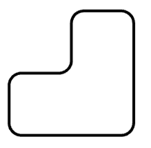
This command is used to create fillets in the intersection points of objects, with automatic dimensioning ability. The command can create fillets individually.
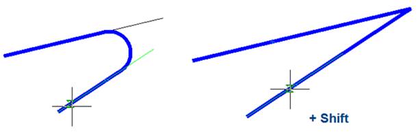
The Fillet command can be used for quick trimming or lengthening of selected objects. To do it, press SHIFT button when you select objects: a current value of fillet radius is temporarily changed to 0 and objects are lengthened or trimmed to intersection point.
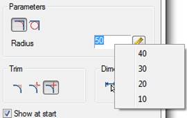
It is possible to make a fillet between parallel segments. A current value of fillet radius is temporarily changed to a value, which equals to half distance between parallel segments. The dialog box opens after the command is launched:
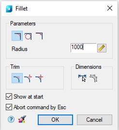
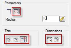
Parameters:
|
|
This button switches on the lines cutting mode. |
|
|
This button switches to insert circle instead of fillet. When performing an operation in this mode, the modes of dimensioning and complete or partial trimming of mating lines are ignored.
|
|
|
Button to enable fillet insertion mode as a mate. |
|
Radius |
Radius of fillet. |
|
|
This button temporarily closes the dialog box to allow measuring of the fillet radius on the drawing. The Value picker dialog appears to perform measurements. |
|
|
This button fully cuts lines before their intersection. |
|
|
This button switches on the mode for cutting of lines before their intersection. |
|
|
This button switches on the mode without lines cutting. |
|
|
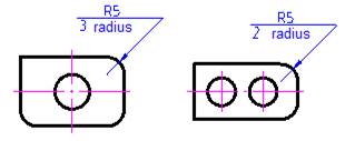
This button switches on the additional dimensioning mode. The button becomes available when the
|
|
|
This button switches the automatic dimensioning mode on/off. |
|
|
This button temporarily closes the dialog box to allow copying of properties from other fillet. The command does not work on fillets created with the participation of a polyline, since when setting up a fillet, all the components are collected into one polyline. |
|
Show at start |
A box that, when unchecked, stops displaying the dialog box for all subsequent command calls, i.e. allows you to reconfigure the command to work in non-dialog mode. To open the dialog box again, select the Properties option in the command line or context menu. This mode of operation is convenient when you often need to use the command without changing its parameters. |
|
Abort command by Esc |
When the box is checked, pressing ESC interrupts the command. When the box is unchecked, pressing ESC displays the Fillet dialog box. |


Double-click or right-click in the fields to enter values will open the context menu with the list of the recently entered values:
Options in the context menu and in the command line are available during the process of fillet creation:
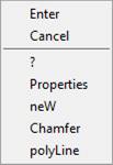
Command options:
|
Properties |
The Fillet dialog box opens to change the chamfer parameters. |
|
neW |
Finishes the creation of one group of fillets and starts another. The command is applied when you need to create some fillets with one radius on one object and with the same radius on another object:
|
|
Chamfer |
Switches to the mode for creating chamfers. The Chamfer dialog box opens to specify the parameters of the fillet. |
|
polyLine |
Constructs fillets for all polyline vertices that are intersection points of two straight-line segments. The operation ignores clipping and dimensioning modes.
|
To create a fillet:
1. Select the first object.
2. Move the cursor over the second object. Fillet options will be presented.
3. If there are no fillet options, select the Properties option from the context menu or the command line and adjust the radius.
4. Select the second object.
5. Select the fillet from the presented options.
Features of the command work
The command works in 3D. To perform the command, the source entities should be located in the same plane.
If you press and hold SHIFT when selecting the second object, then a corner will be formed (closing in the intersection point and cutting off).
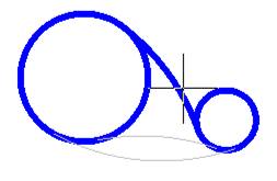
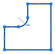
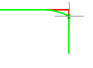
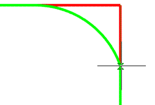
For pairs of objects LINE-ARC, ARC-LINE and ARC-ARC, two types of fillet are available: outside and inside ones.
Outside Inside
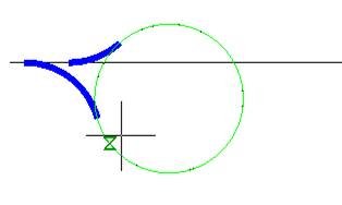
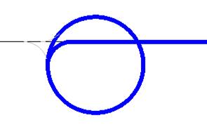
A fillet that combines inside and outside tangency is additionally available for ARC-ARC pair.
|
|
Note |
|
Availability of different types of fillet depends on the fillet radius. Outside and combined fillets require larger radiuses than for inside fillets. |

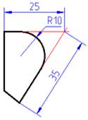
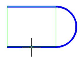
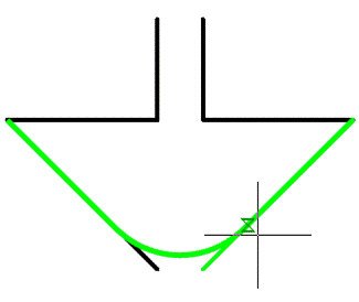
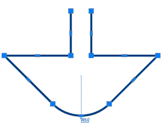
Selecting two parallel lines will create a fillet with a radius equal to half the distance between them (regardless of the specified Length). The sides will automatically align to the longest line.
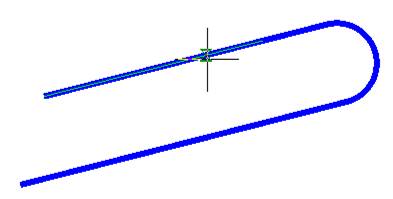
Fillet of parallel lines also works for segments of the same polyline.
A fillet side depends on the mouse cursor position when the second object is selected
When making an insertion of a fillet between neighboring polyline segments, a polyline retains its integrity.
If when using the command, a fillet is created for two polylines, then as a result it will be a single polyline object.
If segments of one polyline separated by other segments are selected, then all these intermediate segments are deleted.
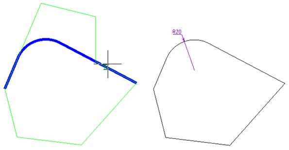
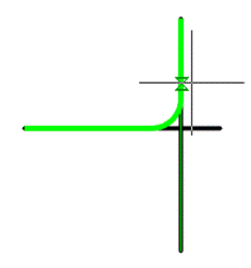
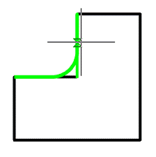
When making a fillet while specifying a second object, a point will be taken at the location of the object and a fillet will be constructed based on this point. Examples of fillets with the same parameters but different specified points:
Fillet Command (Non-dialog Mode)
Command line: F, FILLET
Creates a fillet using the command line.
Command options:
|
? |
Opens additional options for selecting objects. |
|
Undo |
Cancels a previous action in the command. |
|
POlyline |
Creates fillets for all polyline vertices which are the intersection points of two straight line segments. When the Trim option is enabled, fillet lines become new segments of polylines. |
|
RaDius |
Sets the fillet radius. When set to zero, objects are lengthened or cut to intersect. |
|
Trim |
Controls objects cut to fillet lines. Trim -selected objects are removed to the endpoints of the fillet lines. If the objects do not intersect with the fillet line, they are lengthened or clipped to the endpoints of the fillet line. No_Trim – selected objects are not cut. |
|
Multiple |
Adds a fillet to multiple sets of objects. |
Command prompts:
|
Soecify first object or [?/Undo/POlyline/RaDius/Trim/Multiple]: |
Select the first fillet object or the required option to set parameters. |
|
Specify second object or Shift-select to apply corner or [?/RaDius]: |
Select the second fillet object or use Shift key to form an angle in the intersection point. To change parameters, select the required option. |