De
De 

-
-
-
-
-
-
-
-
-
-
-
-
-
-
-
-
-
-
-
-
-
-
-
-
-
-
-
-
-
-
-
Point Clouds Display Settings
-
-
-
-
-
-
-
-
-
-
-
-
-
-
-
Point Clouds Display Settings
 Ribbon: Point Clouds – Settings >
  Switch point cloud boundary
Menu: Point Clouds – Settings > Display point cloud boundary
 Command line: SWITCHPCBOUNDARY
Enable/disable boundary box of each point cloud in the drawing. By default, this mode is turned off, as a result of which bounding contours are not displayed.
Ribbon: Point Clouds – Settings >  Switch point cloud display tree
Menu: Point Clouds – Settings > Display all points
Command line: SWITCHPCDISPLAYTREE
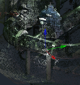
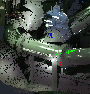
Turns on / off the display of all points in the cloud. Disabled by default, so the number of points displayed on the screen depends on the performance of the PC’s graphics system.
|
|
|
Enabling this mode only affects the speed of displaying clouds and navigation in the workspace. This mode does not affect the speed of clouds processing by commands of stitching (registration), classification, etc. To speed up cloud processing operations, make it sparse with the Thinning the Point Cloud command, which reduces not the displayed, but the actual number of points in cloud. It is also possible to reduce the number of cloud points that get into the document during the import operation by checking the Spacing box and specifying the sequence number of imported points.
Ribbon: Point Clouds – Settings >  Switch point cloud import zoom extents
Menu: Point Clouds – Settings > Zoom extents after import
Command line: SWITCHPCIMPORTZOOMEXTENTS
Auto zoom extents mode to the point cloud after import.
In the majority of cases after importing it is required to zoom to the point cloud. This mode does this automatically. The mode is enabled by default.
Ribbon: Point Clouds – Settings >  Snap Point Cloud
Menu: Point Cloud – Settings > Snap Point Cloud
Command line: SWITCHPCSNAPON
Snap to separate points in Node object snap mode. The mode is enabled by default.
Ribbon: Point Clouds – Settings >  Snap to Edges and Nodes
Menu: Point cloud – Settings > Snap to Edges and Nodes
Command line: SWITCHPCSNAPFEATURES
Allows you to snap to fit points of geometry, recognized in the cloud by features recognition commands.
By default, the mode is on.
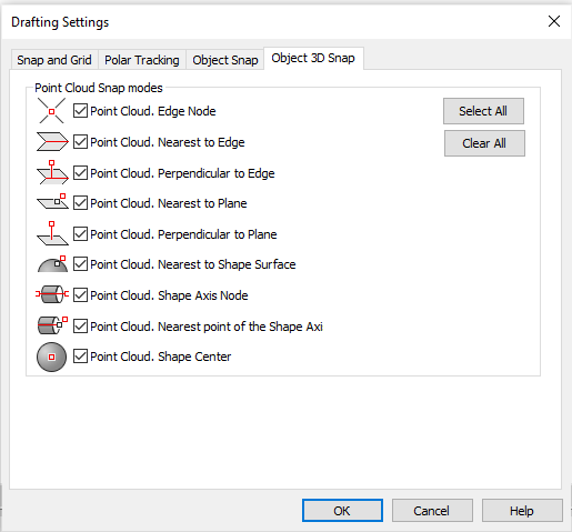
To be able to snap to shapes, the Object 3D Snap mode should be enabled and the required snapping types should be turned on in the Drafting Settings dialog box called from the context menu of  button.