
 De
De  Es
Es  Fr
Fr 

-
-
-
-
-
-
-
-
-
-
-
-
-
-
-
-
-
Visual Styles Editor
-
-
-
-
-
-
-
-
-
-
-
-
-
-
-
-
-
-
-
-
-
-
-
-
-
-
-
-
-
-
-
-
-
Visual Styles Editor
Visual Styles Manager
 Ribbon: View – Visualization – Visual Styles >
  Visual Styles
Menu: View – Visual Styles >  Visual Styles
Toolbar: Main –
 Command line: VISUALSTYLES
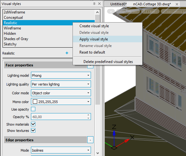
To create, edit, apply, and delete visual styles, use the Visual Styles functional panel.
The top field displays a list of all standard visual styles and the styles of the current document. The options for the visual style selected from the list are displayed below.
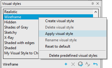
Actions with a visual style
Actions with the selected style are available from the context menu or using the buttons.
|
|
Create visual style |
Creates a new visual style based on the settings of the selected style. Allows you to specify a name and explanation for the new style. It is recommended to create new visual styles rather than changing the settings of the predefined ones. |
|
|
Delete visual style |
Removes the selected visual style. Inbuilt styles and the current viewport style cannot be deleted. |
|
|
Apply visual style |
Applies the selected visual style to the current viewport. When you apply a visual style or change its settings, the corresponding viewport is automatically updated to reflect those changes. Any changes to the current visual style are saved in the drawing. |
|
|
Rename visual style |
Opens the dialog box for renaming the visual style or editing the description. Inbuilt styles cannot be renamed. |
|
|
Reset to default |
Resets the style parameter values to the default ones. |
|
|
Delete predefined visual styles |
Deletes standard visual styles. |


Visual Styles Properties
Face properties
|
Lighting model |
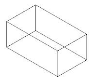
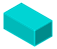
Style of shading for faces, solid fills, and gradient hatches (VSFACESTYLE system variable): · Invisible. Faces seem to be hidden, there is no shading of faces and surfaces. Only the edges of faces are displayed. Used in the Wireframe visual style.
· Constant. Uniform shading without transitions. Hidden line suppression makes invisible lines, edges, and other objects that are actually obscured by objects in the foreground. Used in the Hidden and Sketchy visual styles.
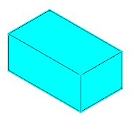
· Realistic. Allows you to achieve a realistic shading effect.
· Gooch. This shading method enhances detail by softening the contrast between highlights and shadows. Warm colors are used in lighted areas, cool colors are used in shaded areas. |
|
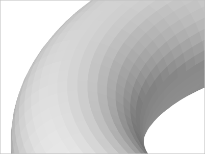
Lighting quality |
Determines the quality of lighting of object faces. Actually sets the color interpolation method for faces of 3D solids and surfaces in the current viewport (VSLIGHTINGQUALITY system variable). No lighting – faces are not lighted. Depending on the value of the Color parameter, objects are colored in one color or another entirely.
Per face lighting – for each face, a specific color is calculated without transitions. Curved surfaces are displayed as a facet approximation.
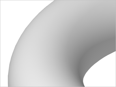
Per vertex lighting – colors are calculated for the gradient transition between the vertices of the faces. The style provides a smooth display without the use of hardware acceleration.
Per pixel lighting – the highest smoothing quality. |
|
Color mode |
Specifies the display of colors on faces. (VSFACECOLORMODE system variable): · No color mode. Does not apply to the face color modifier. · Object color. Faces are displayed in different shades of the object's color.
· Background color. Faces are displayed in different shades of the background color of the current space. · Mono. Faces are displayed in different shades of the color specified by the Mono color option. · Tint. Edges are shaded by changing the tine and saturation values based on the color specified by the Mono color option. · Desaturate. Edges are displayed in different shades of the object's color softened by reducing its saturation by 30%. |
|
Mono color |
Allows you to select a monochrome color or a color tint depending on the color mode of the face (VSMONOCOLOR system variable). The setting has an effect if the face color mode is set to Mono or Tint. |
|
Use opacity |
All objects are displayed semi-transparent. The degree of transparency is controlled by the Opacity % option. |
|
Opacity % |
The degree of opacity of objects: 0% - completely transparent, 100% - completely opaque. Only taken into account when the Use opacity box is checked. |
|
Show materials |
Enables the display of assigned materials. |
|
Show textures |
Enables the display of assigned textures. |

Edge properties
|
Mode |
Method to display edges of objects (VSEDGES system variable): · No edges. Do not display edges. · Isolines. Display by isolines. · Facet edges. Display by face edges. |
|
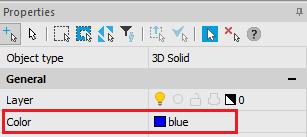
Color |
The color of edges. (VSEDGECOLOR system variable) |
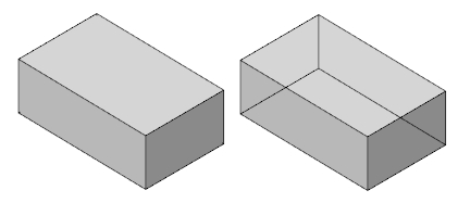
Obscured edge properties
|
Show |
Display object edges hidden by graphics (VSOCCLUDEDEDGES system variable).
|
|
Color |
The color of overlapped edges (VSOCCLUDEDCOLOR system variable).
|
|
Pattern |
The line type for displaying overlapped edges (VSOCCLUDEDLTYPE system variable).
|
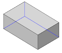
Intersection edge properties
|
Show |
Display intersection edges of 3D objects (VSINTERSECTIONEDGES system variable). Can significantly slow down the work with large drawings. |
|
Color |
Color of intersection edges (VSINTERSECTIONCOLOR system variable). |
|
Pattern |
Line type of intersection edges (VSINTERSECTIONLTYPE system variable). |
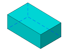
Silhouette edge properties
|
Show |
Display silhouette edges of 3D objects. (VSSILHEDGES system variable). |
|
Width |
The width at which silhouette edges are displayed. (VSSILHWIDTH system variable). |