New in Topoplan
Version 25
- NG_CONVERT_TO_SURFACETIN – Converts a Mesh, a Polyface Mesh and 3D Faces (nanoCAD objects) into a TIN Surface (Civil object);
- NG_CONVERT_FROM_SURFACETIN – Converts a TIN Surface (Civil object) into a Mesh, a Polyface mesh and 3D Faces (nanoCAD objects).
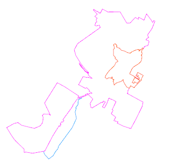
The new command Adding Drawing Objects (NG_MESH_ADD_OBJECTS) adds the following types of objects:

It is possible to save or rebuild triangle edges.
The new command Creating Contour Lines from Objects (NG_MARK_AS_CONTOUR). Now polylines and 3D polylines can be marked as contours, which will allow you to place labels and bergstrings on them.
The new command Create Points by Resection (NG_CREATE_POINT_BY_RESECTION). The first version of the command provided the possibility to create a new point by Reverse angular geodetic resection.
The new command Creating a Coordinate System (NG_NEW_CRS) allows you to set parameters and configure your own coordinate system, which can further be used for recalculation.
The new command Information About Coordinate Systems (NG_CRS_INFO) displays the parameters of all coordinate systems in the Topoplan module database.
Errors in constructing 3D slopes have been fixed.

- calculation of transformation parameters
- calculation of distances and directions on an ellipsoid and on a plane
- recalculation of coordinates between different coordinate systems, including for loaded text files


The replacement of blocks from the classifier if signs were previously selected in the drawing has been fixed. Now it is possible to select options - Replace or Draw a new sign.
The commands for inserting contour labels (NG_CREATE_CONTOUR_LABEL) and bergstrichs (NG_CREATE_BERGSTRICH) have been improved. The possibility to automatically place them along a line has been added. The possibility to select the text style and height has been added for the contour labels command. The possibility to select a block has been added for the bergstrichs command.
New parameters have been added to the Mesh Seal Holes (NG_MESH_SEAL_HOLES) command: the possibility to highlight found gaps and fill them automatically.

A new block in the classifier of Conventional signs (NG_CLASSIFICATOR) for setting non-standard signs for communication lines:

The highlighting of a face and an edge has been added to adding a point to a surface (NG_MESH_VERTEX_ADD).
The possibility to create a layer with a user-defined name has been added to the contour line creation command (NG_CREATE_CONTOUR_LINE).
A new option has been added for the geopoint creation tool (NG_CREATE_POINTS) – creating blocks manually.
The bugs in the command for adding structural lines (NG_MESH_STRUCTURAL_CREATE) have been fixed. The mode for adding multiple objects has been improved.
An option to create points in the beginning and in the end has been added to the command for creating points by interpolation (NG_CREATE_POINTS_BY_INTERPOLATION).
When splitting with the NG_EXPLODE_POINTCLOUD command of a point cloud larger than 100000 points, it is now possible to explode it only into objects - points. For clouds smaller than 100000 points, it is still possible to explode it into geopoints and blocks.
The possibility to add new points beyond the surface boundary has been added to the Add Point (NG_MESH_VERTEX_ADD) and Adding a Group of Points (NG_MESH_VERTEX_ADD_BY_POINTS) commands.
Version 24


It also became possible to add closed structural lines, including with deleting points inside the contour.


- Formatting has been improved;
- Symbols for collapsing groups of elements (arrows) have been added.
It concerns the dialogs for import, export, conversion of geopoints, as well as splitting a point cloud into geopoints.


Version 23


- Group name;
- Description;
- Marker style (of those existing in the drawing);
- Override Marker Style;
- Label Style (of those existing in the drawing);
- Override Label Style;
- Add with Raw Description prefix. The criterion for adding a point to the group. It allows you to add to the group only points with the specified raw description.

The command has no options.
All points with the same raw description are combined into one group. As many groups are created as there are different raw descriptions for geopoints in the drawing. The names of the created groups are the same as the raw descriptions.


- export such objects as geopoints, blocks, simple points to txt, csv, sdr format, with the possibility to create labels in the drawing;
- save the label’s rotation value or other user attributes when exporting to an external file;
- select encoding.


The parameters of the created styles are configured in the Properties bar.


Editing properties of marker styles is started by double clicking on the required marker style in the Drawing Explorer. The parameters are set in the Properties bar.

There are four types of user-defined properties available:
- String: allows you to enter text as a value. Is used when you want to enter any alphabetic or numeric characters.
- Integer: allows you to enter only whole numbers without decimals.
- Double: creates a property that allows you to enter numbers with decimal places.
- Boolean: creates a property that allows you to switch Yes/No (“true” or “false”) value.
Thus, if you have a survey that contains tree data, you can create the Trees classification. Then create user-defined properties related to this classification in it.

For example:
- Name (string),
- Deciduous (boolean),
- Elevation (double).
You can view and edit the values of user-defined properties of the drawing geopoints in the Properties bar.

You can create a new user-defined property classification by selecting Create in the context menu of the Drawing Settings – COGOPoints – User-Defined Property Classification in the Drawing Explorer. The name of the new classification is entered from the keyboard:

You can create a new user-defined property by selecting Create in the context menu of any user-defined property classification in the Drawing Explorer.

User-defined properties can also be assigned during the import of geopoints by the Import Geopoints command.
You can delete a classification or a user-defined property by selecting Delete in its own context menu in the Drawing Explorer.
This allows you to quickly form high-quality underlays from large orthophotomaps, previously divided into component parts.

- Configure coloring gradient;
- Specify minimum and maximum values;
- Set color outside the specified range;
- Select the gradient type (continuous or discrete);
- Save gradient to file and import gradient from file.

- The Additional options have appeared, where you can specify the accuracy of linear and angular units for import;

- The possibility to select encoding has been added.
- The possibility to specify the projection EPSG code to convert imported points has been added.


The imported points will obtain these properties:


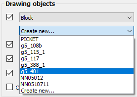
Now, in the geopoints import dialog box, the names of existing blocks are now sorted in order. Previously, when importing geopoints from a TXT file in the form of blocks, the search for the required block took considerable time.
A case sensitivity in the font selection subdialog has been removed.
The situation has been fixed when, while importing several files at once, the creation of entities was repeated as many times as many files was opened.
The incorrect table behavior when importing multiple files has been fixed. With multi-selection of files, changing the beginning of a new line changed the general list, but not the result for each file individually.
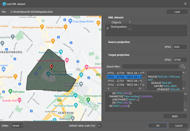
Import from KML/KMZ-format (Keyhole Markup Language) has been realized with the possibility to recalculate data from/ to various topographic and geodetic coordinate systems using EPGS codes (KMLIMPORT command).

- The dialog box, in which the downloaded files are now displayed on the globe, with the possibility to select a map or a satellite image, has been updated.
- Search by number, projection name and display of the selected projection parameters have appeared.
- After importing objects, these objects are zoomed in the drawing.
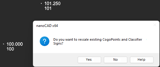
- It has now become possible to select user attributes for obtaining a mark (Z coordinates) when constructing a surface by geopoints.
- Filtering by the angle between edges when creating a surface has been added.

Changing the anchor point of the frame is convenient in case of designing routes, because they can go in any direction. This is also true for tablets, where usually the numbering goes from left to right and from top to bottom. But when you try to insert the second row, it is already inconvenient to use the anchor point from the bottom left.


This is especially important for the A4 landscape format, where the stamp occupies a significant part of the layout and it is difficult to predict whether the model will fit in the future viewport, or its part will be covered by the stamp.


Display of two parameters of the Volume between Models (NG_VOLUMES) command in the Properties bar has been fixed.
A ban on creating custom properties without a name has been introduced.
Such properties as Locked (prohibition of moving, copying, stretching geopoints) and Label Visibility (showing/hiding labels, regardless of the style configured for them) now work in geopoints.
The bug with the appearance of masking when moving a geopoint labe has been fixed.
The possibility to rotate a geopoint label if the label was moved has been added.
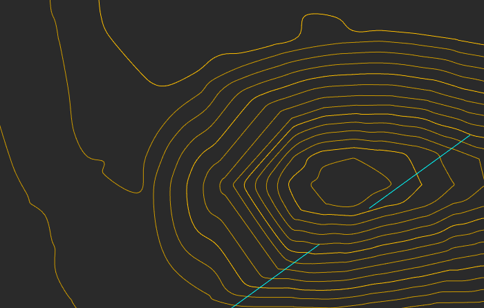
Support for smooth contours on Civil 3D surfaces:
When creating the style of labels (C3D_CREATE_COGO_LABEL_STYLE) and markers (C3D_CREATE_COGO_MARKER_STYLE) for geopoints, the bar is now automatically updated.
Version 22

Each frame carries information about the template, format and scale of the sheet. The design of the future sheet will be taken from the template in accordance with the format.

After the Creating Frames command starts, you can configure the options of future sheet for the frame:

Template – a template file containing a list of available formats with frame design. You can specify a template for formats according to standards or for a topographic tablet.

After selecting a template, specify the sheet size for the inserted frame.
Layout – Allows you to assign a layout format without reassigning the template.
Scale – selection of the topographic scale. By default, the scale of the created sheet is set according to the current TOPOSCALE:

After setting all the parameters, specify the position of the view frame in the drawing. In this case, you can use the nanoCAD precise positioning tools to snap to axial, auxiliary lines, mesh, points, or existing view frames. You can rotate frames and use other standard mechanisms for placing objects in the drawing workspace.
![]() Creating Layouts by Frames (CREATEVIEWFRAMELAYOUT). The command creates layouts for designing a drawing according to previously created frames. Each frame has its own sheet, with the same design, format and scale that were specified when creating the frame.
Creating Layouts by Frames (CREATEVIEWFRAMELAYOUT). The command creates layouts for designing a drawing according to previously created frames. Each frame has its own sheet, with the same design, format and scale that were specified when creating the frame.

The sheet’s frame and stamps are a dynamic block with parameters and attributes that can be edited in the Properties bar or using grips.
It is possible to design in form of GOST and topographic tablets.

For tablets, the Survey plot scheme, or the Sheets combining scheme are created.

![]() Hide Frames (HIDEVIEWFRAMES). Frame hiding mode. Turns off the display of all created frames in the model space. Repeated execution of the command returns the display of frames.
Hide Frames (HIDEVIEWFRAMES). Frame hiding mode. Turns off the display of all created frames in the model space. Repeated execution of the command returns the display of frames.
![]() Delete Frames (DELETEVIEWFRAMES). Deletes all frames created by the Creating Layouts by Frames command (CREATEVIEWFRAME).
Delete Frames (DELETEVIEWFRAMES). Deletes all frames created by the Creating Layouts by Frames command (CREATEVIEWFRAME).


- Unfortified slope;
- Fortified slope;
- Steep coast with a beach;
- Steep coast without a beach;
- Stone retaining walls;
- Wooden retaining walls;
- Ground steep.
Before starting, the command checks the set topographic scale and offers to switch to the 2D-wireframe visual style.

After running the command, set the slope type and characteristics in the Properties bar. The options vary depending on the type of slope and how its edge is specified.

Next, indicate the location of the slope in the drawing. Slope edges can be drawn manually or created from existing drawing lines, depending on the value of the Specify slope edges option. The top and bottom of slope can be closed lines.


You can create a slope from one top point (hill). To do this, instead of specifying points for the slope top, select the Peak option from the context menu or command line.


In the drawing, the slope is selected as a single set of objects, parts of which can be moved.

The command now has the ability to choose when moving a point whether snap to drawing objects or take the height of the mark from the surface;
The command can now take elevation either from a drawing object or from a surface.
When adding surface points, the position of contour lines is now updated, if any have been drawn.
Deleting surface points now updates the position of the contour lines if they were drawn.

![]() Add structure line (NG_MESH_STRUCTURAL_CREATE). The ability to build retaining walls has been added to the command.
Add structure line (NG_MESH_STRUCTURAL_CREATE). The ability to build retaining walls has been added to the command.


![]() Export to LandXML (NG_EXPORT_LANDXML).
Export to LandXML (NG_EXPORT_LANDXML).
It became possible to export geopoints to the LandXML format. When exporting, the belonging of points to a group is saved. Export of geopoints and surfaces is disabled and enabled in the command parameters in the Properties bar.

Now you can open multiple files for import at the same time.
New formats became available for import: CSV, SDR (Sokkia).
You can choose the type of imported objects: blocks \ geopoints \ primitives.
When importing survey files, it is possible to create blocks with the signature of number, mark, code (if available). The scale of blocks depends on the value of the current topographic scale.
If an existing block is selected when creating a point, then a new block with attributes is created, where the point sign is the block that the user has selected. If a new non-existent block is selected, then after the dialog settings, the block editor opens to edit the point sign (circle by default).
You can set layers for each element.
The result table has received additional features:
- Changing the order of points, changing the order of columns. In case of incorrect initial data typing, you can drag one column to another by the header, mutually changing data in these columns;

-
If the corresponding box is checked, it is possible to create a polyline using filtered points;
-
Data filtering by any column is available;

- It is possible to edit point data (name, coordinates, code);

-
If the import is to geopoints, it is possible to create a new group.
-
Multiple editing of cells is available using the SHIFT and CTRL keys. All selected cells are edited simultaneously. For example, you can clear a column if the data is not needed.
Saving of user settings (separators, colors, layers, fonts, etc.) to a file has been implemented.


Styles of labels and markers of coordinate geometry are edited by selecting the desired style in the drawing explorer and then calling the command from the context menu. The properties of the selected style are displayed and changed in the Properties bar.
It became possible to bind to geopoints in the Node mode.

Now a geopoint can be moved with transformation commands: MOVE, ROTATE, ALIGN, etc.

An archive of measurement files contains raw or preprocessed data, while a set of prepared underlays should be groups of geopoints ready for use in projects.
Filling the archive of measurement files
Measurement files are stored in the Geofiles folder. The path to the folder is defined in the Standard directories section of the Options dialog.
To add a file to the archive, the
If you need not only to save a raw file, but to carry out a full import at this stage, so as not to return to setting parameters later, then you should use the
The measurement archive is displayed in the file explorer in Geofiles folder. By expanding it, you can view all archive measurement files.
Creating selections and forming a set of underlays
To work with points, it is necessary to form selections from the measurement archive.
Selections are formed by special commands in the form of separate DWG files, which are subsequently placed as external references in working drawings. Thus, the same selection (underlay) can be inserted into several different working DWG files.
To form a selection:
- Create a new underlay with the
 Attach geounderlay command.
 - Import the required measurements into it from the archive using the
 Import measurements command.
 - Configure groups of points, forming them, if necessary, and setting their parameters (styles). Enable/disable the visibility of the desired groups.
- Save the drawing to the collection of underlays as a separate named entity using the
 Save as geounderlay command.
The underlay collection is a separate Geofiles folder. The path to the folder is defined in the Standard directories section of the Options dialog.
It is also visible in the File Explorer as the Geofiles folder. By expanding it, you can view all the underlay files.
Before drawing conventional signs, select one of the topographic scales: 1:500, 1:1000, 1:2000 or 1:5000, in accordance with the required scale of the finished drawing.

The bar elements are structured by thematic sections and in alphabetical order.

The capabilities of the Conventional signs bar are not limited to inserting signs from an existing classifier. It is also possible to create your own signs or connect third-party libraries. To do this, use the buttons at the top of the bar.
Create element. Creating a new element of the library.
Create section. Creating a folder for thematic ordering of library items.
Create library. Prompts for a name in the command line and creates a new empty library with two ordering options: thematic and alphabetical.
Attach/detach library. Opens a dialog box that allows you to enable/disable the display of existing libraries in the Conventional signs bar. The source library cannot be disabled.
It is also possible to create new thematic sections, edit the composition of elements included in them, as well as delete any sign or section from the library.


 De
De  Es
Es  Fr
Fr 
