
 De
De 

-
-
-
-
-
-
-
-
-
-
-
-
-
-
-
-
-
Viewports of Model Space
-
-
-
-
-
-
-
-
-
-
-
-
-
-
-
-
-
-
-
-
-
-
-
-
-
-
-
-
-
-
-
Viewports of Model Space
Model space can be separated into several rectangular non-overlapping areas called viewports.
Non-overlapping areas fill in model space and cannot be placed over each other. When starting a project, usually one viewport, filling in all the model space is used. This viewport can be separated into several viewports and different fragments of the drawing, or model views can be displayed on every viewport at the same time. The changes made in one viewport are also shown in the whole drawing (in other viewports). You can switch between viewports at any time, even whilst a command is being performed. To switch to another viewport, click at any point on the screen. The cursor is displayed in the current viewport – the common arrowhead is displayed in all the other viewports.
For every viewport you can specify the display scale, pan the viewport image independently of the other viewports, specify UCS and display the modes of grid and snap usage. You can save the setting parameters of any viewports to use them again and restore an image of any viewport.
Only one non-overlapping viewport can be printed.
Configuration of non-overlapping viewports can be different:
 Ribbon: View – Model Viewports – Viewport Configuration >
  Single
Menu: View – ViewPort >  1 Viewport
Toolbar: ViewPorts >
 Command line: VIEWPORT_SINGLE
In Model Space: restores the configuration to one viewport (the view is taken from the last active window).
In Paper Space: creates one viewport.
Ribbon: View – Model Viewports – Viewport Configuration >  Two: Vertical
Menu: View – ViewPort >  2 Viewports Vertical
Toolbar: ViewPorts >
Command line: SPLITVIEWPORT_VERTICAL
Creates a configuration of two vertical viewports.
Ribbon: View – Model Viewports – Viewport Configuration >  Two: Horizontal
Menu: View – ViewPort >  2 Viewports Horizontal
Toolbar: ViewPorts >
Command line: SPLITVIEWPORT_HORIZONTAL
Creates a configuration of two horizontal viewports.
Command line: SPLITVIEWPORT_3
Creates a configuration of three viewports.
After starting the command, there is a prompt in the command line:
Enter an option [Horizontal/Vertical/Left/Right/Top/Bottom]<Right>
Command options:
|
Horizontal |
Creates a configuration of three horizontally placed viewports. |
|
Vertical |
Creates a configuration of three vertically placed viewports. |
|
Left |
Creates a configuration of three viewports, one of which is placed to the left and the others – to the right. |
|
Right |
Creates a configuration of three viewports, one of which is placed to the right and the others – to the left. |
|
Top |
Creates a configuration of three viewports, one of which is placed at the top and the others – at the bottom. |
|
Bottom |
Creates a configuration of three viewports, one of which is placed at the bottom and the others – at the top. |
3 Viewports Horizontal
Ribbon: View – Model Viewports – Viewport Configuration >  Three Viewports Horizontal
Menu: View – Viewports >  3 Viewports Horizontal
Toolbar: Viewports –
Command line: SPLITVIEWPORT_3_HORIZONTAL
Creates a configuration of three horizontal viewports.
3 Viewports Vertical
Ribbon: View – Model Viewports – Viewport Configuration >  Three Viewports Vertical
Menu: View – Viewports >  3 Viewports Vertical
Toolbar: Viewports –
Command line: SPLITVIEWPORT_3_VERTICAL
Creates a configuration of three vertical viewports.
3 Viewports Left
Ribbon: View – Model Viewports – Viewport Configuration >  Three Viewports Left
Menu: View – Viewports >  3 Viewports Left
Toolbar: Viewports –
Command line: SPLITVIEWPORT_3_LEFT
Creates a configuration of three viewports, one on the left and two on the right.
3 Viewports Right
Ribbon: View – Model Viewports – Viewport Configuration >  Three Viewports Right
Menu: View – Viewports >  3 Viewports Right
Toolbar: Viewports –
Command line: SPLITVIEWPORT_3_RIGHT
Creates a configuration of three viewports, one of which is located on the right, and two on the left.
3 Viewports Top
Ribbon: View – Model Viewports – Viewport Configuration >  Three Viewports Top
Menu: View – Viewports >  3 Viewports Top
Toolbar: Viewports –
Command line: SPLITVIEWPORT_3_ABOVE
Creates a configuration of three viewports, one at the top and two at the bottom.
3 Viewports Bottom
Ribbon: View – Model Viewport – Viewport Configuration >  Three Viewports Bottom
Menu: View – Viewports >  3 Viewports Bottom
Toolbar: Viewports –
Command line: SPLITVIEWPORT_3_BELOW
Creates a configuration of three viewports, one at the bottom and two at the top.
Ribbon: View – Model Viewports – Viewport Configuration >  Four: Equal
Menu: View – ViewPort >  4 Viewports
Toolbar: ViewPorts >
Command line: SPLITVIEWPORT_4
Creates a configuration of four similar viewports.
Ribbon: View – Model Viewports –>  Named
Named
Menu: View – Viewports >  Named Viewports
Toolbar: ViewPorts – Viewports
Toolbar: Layout – Viewports
Command line: VIEWPORTS, VPORTS
The command opens the Viewports dialog box.
On the New Viewports tab you can create the required configuration of viewports on the standard base and save it for further usage:
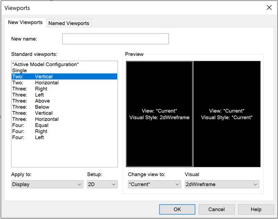
Parameters:
|
New name: |
Name of the saved configuration of viewports. |
|
Standard viewports: |
List of standard configurations of viewports. |
Apply to:
|
Display |
Applies the selected configuration of viewports to the whole Model Space. |
|
Current viewport |
Applies the selected configuration of viewports to the current viewport. |
Setup:
|
2D |
Sets the selected configuration as the current viewport for all viewports. |
|
3D |
Sets the selected configuration of standard model views for all viewports. |
|
Preview |
Preview of the selected configuration of viewports. The current viewport is shown with a double frame. |
|
Change view to: |
Changes the view of the common viewport. There are existing named views of the drawing in the drop-down list (there are additional standard model views for 3D mode). |
|
Visual style: |
Changes the visual style of the selected viewport. The available styles in the drop-down list are: · *Current* · 2D Wireframe · Conceptual · Realistic · Wireframe · Hidden · Shades of Gray · Sketchy · X-ray · Shaded with edges · Shaded · Monochrome |
To change a view or a visual style for a viewport:
1. Double click to select the viewport in the Preview window (selected object is shown with double frame).
2. Select the required view or visual style from the drop-down list.
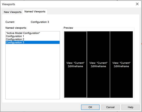
If a name was specified during the creation of the configuration of the viewports, the configuration will be saved as a named configuration. A named configuration of viewports can be used without preset.
The list of created and saved configurations is shown on the Named Viewports tab:
To create a configurations of viewports:
1. Select a standard configuration in the New Viewports tab.
2. In the New name enter a configuration name.
3. Select OK.
The name of the created configuration is shown in the Named viewports section of the Named Viewports tab when the Viewports dialog is opened next time.
The Save Configuration command from the View>Viewports menu allows a name to be specified in the command line for the current configuration of viewports.
To restore a configuration of viewports:
1. Select the required configuration in the Named viewports list (after selection, a list of viewports will be selected in the Preview window).
2. Select OK.
Or:
IDH_RestoreViewportCFG
1. Start the Restore Configuration command (the View>Viewports).
2. In the command line, type the configuration name as an answer to the prompt Enter viewport configuration name: (the list of available configurations is shown in the command line’s protocol).
3. Press ENTER to finish the command.
To rename a configuration of viewports:
1. Select the required configuration in the Named viewports list (after selection, a list of viewports will be selected in the Preview window).
2. Select the Rename option from the context menu.
3. Enter a new configuration name.
4. Press ENTER or click on any place of the section except the renaming field to finish the command.
5. Select OK.
To delete a configuration of viewports:
Select the required configuration in the Named viewports list (after selection, a list of viewports will be selected in the Preview window).
2. Select the Delete option from the context menu.
3. Select OK.
Or:
IDH_DeleteViewportCFG
1. Start the Delete Configuration command (the View>Viewports).
2. In the command line, type the configuration name as an answer to the prompt Enter viewport configuration name: (the list of available configurations is shown in the command line’s protocol).
3. Press ENTER to finish the command.