
 De
De  Es
Es  Fr
Fr  Pt
Pt 

-
-
-
-
-
-
-
-
-
-
-
-
-
-
-
-
-
-
-
-
-
-
-
-
-
-
-
-
-
-
-
-
-
Section Note
-
-
-
-
-
-
-
-
-
-
-
-
-
-
-
-
-
-
-
-
-
-
-
-
-
-
Section Note
 Ribbon: Home, Annotate – Leaders >
  Section note
Menu: Draw – Notes >  Section notes…
Toolbar: Utilities, Notes –
 Command line: NOTES
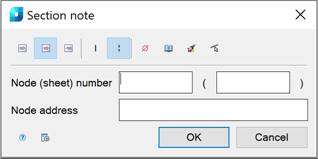
This command opens the Section note dialog box to set the note options:
Options:
Use the icons to select the text alignment method:
|
|
|
By left edge. |
|
|
|
By center. |
|
|
|
By right edge. |


Use the icons to select the secant type:
|
|
|
Single-stroked line. |
|
|
|
Double-stroked line. |


Other icons and options:
|
|
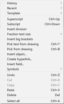
The Insert special symbol icon opens the panel with the table of special symbols, to select and insert them at the current cursor position in the text input field. |
|
|
The Notepad icon opens the Notepad dialog box. |
|
|
The Match properties icon temporarily closes the dialog box to specify the inserted leader whose properties should be copied and applied to the newly-created leader. |
|
|
The Select line icon is used to override the first and second lines of breaking construction. The icon is available when you edit the node secant note inserted into the drawing. |
|
Node (sheet) number |
An input line consisting of two fields to indicate the Node and Sheet number. |
|
Node address |
Input line to specify the Node Address. |
|
|
The Options button opens the nanoCAD Design Settings dialog box – Symbols tab |


The Section note leader contains two input lines by default. The first input line consists of two fields for specifying the Node (sheet) number. The second input line is for specifying the Node Address.
Right-click in the text field and choose the required menu item:
When you open the context menu on a leader arrow (without selecting the leader), a dialog box for selecting the arrow type will appear:
 .
.
To create a section note:
The Show dialog before inserting the object option is enabled
1. Run the command.
2. In the Section note dialog box, select the required note options.
3. Click OK.
4. Enter the required text into the text fields
5. Specify the first line of the structure to be cut, perpendicular to which the section line of the leader will be located. To select an object, take the sElection command in the command line or the context menu. To freely specify a point on the drawing, select the frEe command. The modes are switched by pressing the SPACEBAR key.
6. Specify the second line of breaking construction.
7. Specify the landing position on the drawing.
The Show dialog before inserting the object option is disabled
1. Run the command.
2. Specify the first line of the structure to be cut, perpendicular to which the section line of the leader will be located. To select an object, take the sElection command in the command line or the context menu. To freely specify a point on the drawing, select the frEe command. The modes are switched by pressing the SPACEBAR key.
3. Specify the second line of the structure to be cut.
4. Place the leader landing on the drawing.
5. In the Section note dialog box, select the required note options.
6. Enter the required text into the text fields.
7. Click OK.