
 De
De  Es
Es  Fr
Fr  Pt
Pt 

-
-
-
-
-
-
-
-
-
-
-
-
-
-
-
-
-
-
-
-
-
-
-
-
-
-
-
-
-
Offset Dimension
-
-
-
-
-
-
-
-
-
-
-
-
-
-
-
-
-
-
-
-
-
-
-
-
-
-
Offset Dimension
 Ribbon: Home, Annotation – Dimensions >
  Offset Dimension
Menu: Dimensions –  Offset Dimension
Toolbar: Utilities, Dimensions –
 Command line: dimoffset
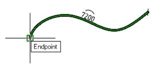
The command allows you to construct a dimension similar to the outline of the selected object. Offset dimension is indicated by an arc over the value.
To set an angular offset dimension:
1. Select the method for specifying the object in the command line or context menu. The frEe method is used in paper space when it is necessary to set a dimension on an object located in an inactive viewport. In all other cases, the sElection method is used.
2. Specify the object from which the dimension will be created. The selected object can be: segment, arc, spline, polyline, circle or ellipse.

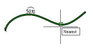
Specify the first insertion point (the starting point of the dimension).
3. To automatically set dimensions at the end points along the entire length of the object, press the SPACEBAR key or right mouse button (does not work for closed objects).
4. Specify the second insertion point (the end point of the dimension reference), if the SPACEBAR or the right mouse button was not pressed.
5. Select the location of the dimension line. Left-click to fix the selected position:
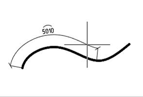
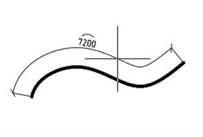
The command will continue to work in a cyclic mode. To exit the cyclic mode, press the Esc key.
Smart grips for offset dimension
1. Dimension value placement grip.
2. Extension line position grips.
3. Dimension endpoint grips.